Blog

CE Tech Tips — September 2019

**NOTICE**
Due to the danger and complexity of electronic equipment repair, the following technical tip is intended for professional reference only. Please refer to manufacturer’s recommendations as Encompass does not guarantee the accuracy, reliability or safety of this information. 

Hitachi TV,  42HDS52A
Reason for Service: Loud buzz comes from right speaker, nothing from left.
Solution: Replacing sub digital board fixed set.

Mitsubishi TV, WD-65835
Reason for Service: Dead set, no LEDs blinking or on.
Solution: If 12V and 21V supplies are okay, replace main board.

Panasonic TV, TH-50PZ77U
Reason for Service: 12 blink error code
Solution: Might be bad speaker. Ohm them and if one is low, unplug speaker and try set again.

Philips TV, 50PF7321D/37
Reason for Service: Dead set, clicks when plugged in.
Solution: Found two bad caps on power supply board: C8059 and C8060. Both 3300uF/10V.

Samsung TV, LN46D550K1FXZA
Reason for Service: No backlights
Solution: Replaced inverter board: 27-D056702

Sharp TV, LC-C3242U
Reason for Service: No power.
Solution: Check for shorted 5W/150V zener in power supply.  Also check R7002, 2.2ohm/half W.

Sony TV, KDL55EX621
Reason for Service: Shuts down with two blink error code.
Solution: Replaced Q6602 & Q6603 on G8 board, and R6540 on G6 board.  0.1ohm/half W.

Vizio TV, E421VA
Reason for Service: When set turned on, logo goes from amber to white for just a second, then the set shuts down.
Solution: Replacing the power supply fixed the problem.


Encompass to Manage Repair Parts Distribution for Sound United

Deal includes parts for popular electronics brands Denon, Marantz, Boston Acoustic

Lawrenceville, Ga., August 22, 2019Encompass Supply Chain Solutions, Inc., a leading provider of replacement parts and supply chain services for a diverse range of product brands, today announced it has implemented a comprehensive parts supply chain management program to support Sound United and its full complement of consumer electronics brands.

Under an agreement with Sound United – an industry leader in home theater and personal audio products – Encompass manages its entire parts supply chain, including parts forecasting, purchasing, warehousing, distribution and call center service. Encompass also serves as a master supplier to Sound United’s authorized service providers, self-maintaining retailers and other designated affiliates.

The agreement comprises parts support for all Sound United brands: Denon®, Marantz®, Polk Audio, Classé, Definitive Technology, Polk BOOM, HE OS® and Boston Acoustics®. Encompass previously served as an authorized parts distributor for Sound United and currently maintains special ecommerce portals for Denon and Marantz to streamline parts access.

The program will be supported through Encompass’ Florida, Georgia and Nevada facilities to expedite delivery throughout the U.S.

“Encompass has supplied parts for Sound United brands for many years,” said Encompass Senior Vice President of Business Development Joe Hurley. “We appreciate the opportunity to further leverage our experience to enhance parts availability and turnaround time. Our goal is to provide superior aftersales service to help reinforce consumer loyalty to Sound United products.”

Hurley said the program will be continually assessed through performance metrics co-developed with Sound United. Encompass will be measured on such indicators as same day shipments, fill rates, order accuracy, returns processing and more.

“Monitoring and reporting on KPIs [key performance indicators] is critical to instilling confidence in our clients that their programs are running smoothly, and customers are being well served,” said Hurley. “Encompass provides full visibility to our clients in real time so they know what’s happening at any stage.”

About Encompass Supply Chain Solutions, Inc.

Formed in 1953, Encompass is one of the country’s largest suppliers of repair parts and accessories for products throughout the home. Encompass also offers complete parts supply chain management, 3PL, depot repair and reverse logistics service. In addition to consumers, we support an array of B2B customers, including manufacturers, multi-family property management, warranty providers, service networks, independent dealers and retailers.

For more information, please visit solutions.encompass.com and follow us on LinkedIn, Facebook and Twitter.

CONTACT: Kristin Hurst, Director of Marketing & Communications

CE Tech Tips — August 2019

**NOTICE**
Due to the danger and complexity of electronic equipment repair, the following technical tip is intended for professional reference only. Please refer to manufacturer’s recommendations as Encompass does not guarantee the accuracy, reliability or safety of this information. 

Hitachi TV, 46UX12B
Reason for Service: Set shuts down.
Solution: Replaced Q401 & D441.

Panasonic TV, TC–P50X5
Reason for Service: Dead set, no power.
Solution: Replacing U203 on foil side of board fixed set.

Pioneer Pro150FD TV
Reason for Service:  Dead, two blink error.
Solution: Replaced power supply.

Samsung TV, PN64E533D2FXZA
Reason for Service:  Dead set, main fuse was blown.
Solution: Replaced shorted QS802, QS804 on power board.

Samsung TV, PN64E533D2FXZA
Reason for Service: Dead set.
Solution: Found two bad FETs: QS802 & QS804. Fuse also blown: F801.

Sanyo TV, DP50749-01
Reason for Service: Dead set.
Solution: Found shorted IC301, STR-W6252 and open fuse, 302, 1A. Replacing both fixed set.

Visio TV, VP50HDTV10A
Reason for Service: No picture, no prime but has audio.
Solution: Found open resistor, R135, on Y-SUS.  1ohm/5W ceramic.

Westinghouse TV, TX-42F430S
Reason for Service: Won’t turn on, but standby okay.
Solution: Replaced cap TC51 in power supply, 470uF/16V.

LG Dryer Faulty Gas Burner Valve Assembly

**NOTICE**
Due to the danger and complexity of electronic equipment repair, the following technical tip is intended for professional reference only. Please refer to manufacturer’s recommendations as Encompass does not guarantee the accuracy, reliability or safety of this information. 

How to Replace a Faulty Gas Burner Valve Assembly in a LG Dryer

If clothes are still wet after completing the dry cycle in LG dryer model DLG2602R, it is likely due to lack of heat. This is a common dryer issue that could be caused by numerous possible malfunctions.

Once determining there are no issues with the high limit thermostat, flame sensor, thermistor and ignitor, consider examining the gas burner valve assembly, which supplies gas to the dryer burner. A malfunctioning valve assembly won’t administer gas, which means the dryer won’t heat.

Before starting any dryer repairs, unplug it from the wall and turn off the gas supply valve. Never attempt a repair without wearing proper safety gear, such as work gloves and goggles. As with all technically difficult and potentially dangerous repair, this repair is best left to a
specialist.

Steps to Replacing Gas Burner Valve Assembly

  1. Pull LG dryer forward and away from laundry room wall. On the back of the appliance, unthread screws that secure the top panel to  dryer. Once screws are out, pull panel toward you, and lift it up and off dryer.
  2. Now, disassemble the control panel. (Before disconnecting wires, it’s a good idea to take a photo of all wire connections to assist in easily reconnecting them during reassembly.) Start detaching the wire harnesses from the back of the board. Once all wires are disconnected, take out the screws that hold the control board console to the dryer, and then pull console off front of dryer.
  3. With control board removed, disconnect the door switch located near the top center of the door frame. Next, open dryer door and
    unthread screws that hold front panel to lint screen housing. Once the screws are out, close the door and unthread screws at the top of the front panel. Then, carefully tilt front panel backward, and pull it up and off dryer.
  4. Now, remove control panel bracket off the dryer. First, locate dryer light bulb and disconnect wire harness running to it. Next, locate two wiring retaining clips on the back of the bracket. Take out the wires being held in the retaining clips. Then, remove screws holding the control panel bracket to the front of dryer, and pull bracket off dryer.
  5. Near the bottom of dryer, disconnect wire harness to the moisture sensor. Once the wires are separated, unthread screws that
    secure bulkhead to dryer and carefully lift off.
  6. Reach in between dryer floor and dryer drum to take drive belt off idler pulley and drive motor pulley.
  7. Grab drive belt on top of dryer drum and use to help guide drum out of dryer cabinet.
  8. With drum removed, locate gas burner valve assembly in the cabinet’s lower right hand corner. Disconnect wire harnesses running to valve assembly terminals. With a Phillips screwdriver, unthread screws that secure gas line to burner valve. Once screws are loose, carefully pull gas line off burner valve. Next, take out screws holding valve assembly to mounting bracket, and then take gas burner valve off mounting bracket and out of dryer cabinet.
  9. Before installing new valve, take the orifice off the old gas burner valve and place on new component. Once orifice is securely
    attached to the new gas burner valve assembly, proceed with installation process.
  10. Place gas burner valve assembly on mounting bracket, ensuring screw holes are lined up on bracket with screw holes on the valve
    assembly. Then, replace screws used to secure gas burner valve to mounting bracket. Next, align gas supply tube with burner valve, and insert tube into the valve. Once tube and valve are connected, rethread screws taken out earlier to secure the tube to the valve. To complete installation, reconnect gas burner wire harnesses to valve terminals.
  11. Before putting dryer back together, take a moment to check for any gas leaks. To do so, fill a spray bottle with soapy water, and turn  gas supply valve back on. Then, spray gas burner valve with soapy water. If any bubbles form, a gas leak is present, meaning the connection is not tight enough. At this point, turn off dryer’s gas supply, and try tightening the tube and valve coupling. Once you’ve adjusted the union, turn gas back on, and run gas leak test again. If no bubbles appear, the gas leak should no longer be an issue. If bubbles are still forming, DIY consumers should contact a dryer repair technician to further inspect.
  12. After testing for leaks and none are found, turn off gas running to the dryer, and start reassembling the dryer. Pick up dryer drum and carefully guide it into the dryer cabinet, ensuring the drum back sits on the drum rollers. Then, reach in between the drum and dryer floor to rethread drive belt on idler pulley and drive motor pulley. Make sure belt is installed in zigzag formation.
  13. Retrieve dryer bulkhead, and align with front of dryer. Then, secure part with screws taken out earlier. With bulkhead in place,
    reconnect moisture sensor wire harness, and light bulb wire harness.
  14. Now, reattach control board bracket. Once bracket is in place, pull door switch wire harness to front of dryer through one of the
    openings on the bracket. Then, snap wire into retaining clips on back of the bracket.
  15. Grab dryer front panel and line up with the dryer front. Before laying panel flush, reconnect door switch harness to door switch, and
    finish installing front panel. After adding screws to secure panel, open dryer door, and rethread screws that connect front panel to lint screen housing.
  16. Snap control panel back on dryer, and reattach screws removed earlier. Finish installing control panel by reconnecting wire harnesses that run to the panel back.
  17. Finally, reinstall the dryer’s top panel, plug in the dryer and turn on gas supply valve.

Special thanks to Fred’s Appliance Academy for this helpful tip!


CE Tech Tips — July 2019

**NOTICE**
Due to the danger and complexity of electronic equipment repair, the following technical tip is intended for professional reference only. Please refer to manufacturer’s recommendations as Encompass does not guarantee the accuracy, reliability or safety of this information. 

Hitachi TV, 57UWX20B
Reason for Service: Shuts down.
Solution: Horz output voltage and B+ okay; Horz output transistor collector has distorted waveform.  Replace TH01.

JVC TV, LT32DM20
Reason for Service: Set starts with OSD showing input, then shuts down.
Solution: One of the inverter transformers was bad; replacing it fixed the set. Found it by comparing to other transformers.

Panasonic TV, TH-50PZ80U
Reason for Service:  No picture or OSD after powering on; power light lit.
Solution:  Replacing A board fixed set.

Samsung TV, HLP5085WX/XAA
Reason for Service: Set makes squealing noise when powering on.
Solution: Replaced C540, 1uF/50V SM cap on DMD module.

Samsung TV,  LN-T3753HN
Reason for Service: At turn on, backlight flashes for short time, then no more backlight.
Solution: Replaced inverter.

Sony TV, KDL46W5150
Reason for Service: Set comes on for 10 seconds, then shuts down. Does this three times then gives 10 blink error code.
Solution: Try factory reset.  Turn power on, then immediately press and hold arrow up and press and release power button.

Vizio TV,  VP322HDTV10A
Reason for Service: No audio.
Solution: Replacing SM Q15 fixed problem.

Westinghouse TV, LD-3255VX
Reason for Service: Dead set.
Solution: Replacing U13/14 eeprom fixed set. TW61301-K032A69

How to Replace LG Washer Circulation Pump Motor

**NOTICE**
Due to the danger and complexity of electronic equipment repair, the following technical tip is intended for professional reference only. Please refer to manufacturer’s recommendations as Encompass does not guarantee the accuracy, reliability or safety of this information. 

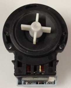
One of the most important parts of a washing machine is the circulation pump motor. When this part isn’t operating correctly, water isn’t circulating and clothes come out of the wash and rinse cycles still dirty. To replace this part,  order part #EAU61383503.

Following are the installation instructions:
1. Unplug washer and turn off the two water connections.
Please note the first step to any repair is unplugging the appliance. This is especially important when you need to disassemble the machine to reach interior parts. Also, turn off water connections to minimize the risk of a water leak, and pull the appliance away from the wall.

Depending on available space, you may also want to disconnect the water lines and pull the drain line connection out of the wall. During this repair, the machine must be tilted back to reach the circulation pump motor.

2. Disassemble machine to remove front access panel.
Locate pump filter in bottom left corner of machine. Remove door by opening and popping hinges free. Pull black hose out of clip and then remove hose cap. There may be water, so have a towel handy. Next, remove screw that secures pump filter housing in place. Remove housing, then loosen screw beneath that secures front panel to machine frame. Remove the outer boot seal.

Open door, and pry out wire clamp.  Pull outer edge of seal out from edge of front panel. Loosen screw securing door latch mechanism to right side, and then reach past seal around back of front panel to pull mechanism inside machine and out of the way. Then, close door and remove top access panel. At rear of the machine, remove two screws holding top panel to rear brackets. Slide top panel back, lift up and set aside.

Next, remove dispenser drawer at top left corner of control panel. You may have to reach in to depress back tab. Then, remove screw holding housing in place and push inside away from the front panel.

Remove control panel by taking out screw located at right interior side of control panel. Loosen ties holding lengths of wires flush and together against control panel. Unplug the three wire harnesses.

Next, peel the control panel away from front panel starting at top right corner. Once top is loose, tilt it forward to carefully pull wires out of cutout, and set aside. Lean against door and front access panel to hold in place. Then, remove screws along top of front access panel where control panel used to be. Tilt panel forward, lift free of bottom groove, and set aside.

3. Remove existing circulation pump motor.
Locate circulation pump motor in bottom left corner to right of green and cream hoses. Before removing parts, set a box behind the washer and tilt machine back at 45-degree angle for easier access to parts. Don’t pinch hoses and drain lines on the back.

Next, remove two wire harnesses from assembly. Also, remove retaining clip from assembly. Remove three screws that hold pump motor up against housing. The whole part should now come out. Be sure to take a picture of the screws and wires to have a helpful guide when realigning during reassembly.

4. Install new circulation pump motor.
Remove protective shield from part and snap into place around new circulation pump motor. Orient new pump motor so seal fits into housing. Press into place and re-secure all three screws. Next, reattach black and blue wires according to the picture (with black wire on bottom or right port and blue wire on top or left port) and ensure excess lengths of wires are securely held in place in retaining clip.

5. Reassemble washer.
First, pull washer back into standing position so it’s upright. Next, reattach front panel by setting on bottom groove. Tilt it flush with panel front, and lean against it to hold in place while securing top in place with screws.

Now reattach control panel. Set bottom edge against frame and slide wires through the cutout. Tilt panel up flush against frame and snap locking tabs shut. Tighten screw in top right corner inside machine. Then, reattach two wire harnesses on interior sides of machine. Then, slip wires against control panel back and tighten ties to secure wires.

Next, push  dispenser housing back into position in  front opening and secure in place with the two screws. Push drawer back into position and close it.

Set top panel on top of machine, but leave an inch or so hanging over back edge. Slide along rails so it snaps into position under front edge of control panel. Retighten the two screws on back bracket. At front of the machine, push door switch assembly back through cutout on right side of door opening and secure mechanism with the two screws.

Pull seal back into place around the opening. Press edges into groove and run your hand along entire circumference to check for gaps or loose sections. It should snap into place along the lip. Next, install wire clamp into the groove. Orient spring at the bottom and work counterclockwise from there to press into the groove. Once it’s too tight to pull into position by hand, use pliers to stretch the spring and push the extended wire into place around remainder of the circle. Tug on the seal to make sure it’s secure. The clamp and spring should note be visible.

Shut the door and reattach screw in the filter pump cutout to hold everything in place. Then, replace housing and attach with second screw. Reattach drain hose lock to black hose and fold hose back up into retaining clip. Reattach door by snapping hose into position.

Reconnect water lines by retightening them to inlets on the back of the machine and reinsert drain hose to wall connection. Turn on the two water connections, push the washer back into position, and plug washer back in.

Special thanks to Fred’s Appliance Academy for this helpful tip!


CE Tech Tips — May 2019

**NOTICE**
Due to the danger and complexity of electronic equipment repair, the following technical tip is intended for professional reference only. Please refer to manufacturer’s recommendations as Encompass does not guarantee the accuracy, reliability or safety of this information. 

Hitachi TV, 60SX2K
Reason for Service: Loss of color
Solution: Replaced X-501 and C508.

Magnavox 32MF30301B
Reason for Service: Power supply fix
Solution: Replace the following: Q600 & 601, D607, 610 & 640,  R608 & F601.

Panasonic TV, H50PE70U
Reason for Service: Set shuts down when trying to turn on.  Shows 12 blink error code.
Solution: Ohm speakers for a short, unplug it if one is found, then try set again.  Replace shorted speaker.

Philips TV, 40PFL3705D/F7 (Serial # beginning with YA1)
Reason for Service: No picture, but has backlight and audio
Solution: F100 on panel controller board was bad.  Replace with 3.15A SMD.  #PNF10148.

Sanyo TV, DP42647
Reason for Service: Set has black screen, but sound okay
Solution: Found shorted diode on T-Con board: CP4, SR34

Sharp TV, LC-52C6400U
Reason for Service: Dead; error, one long, one short.
Solution: Found bad diode on power board: D7805.  MUR460.

Sony TV, KDL-40V4100
Reason for Service: Picture solarized
Solution: Look for bad AS15 chips on T-Con.

Toshiba TV, XV645U
Reason for Service: Dead set; all fuses okay
Solution: Replacing IC Q880 fixed set.  STRY6456.

Vizio TV, L37HDTV10A
Reason for Service: Set locks up when going to tuner setup on digital input.
Solution: Replaced digital tuner board, #3370-0052-0187.