Author - wpengine

How to Repair Leaking GE Washer

**NOTICE**
Due to the danger and complexity of electronic equipment repair, the following technical tip is intended for professional reference only. Please refer to manufacturer’s recommendations as Encompass does not guarantee the accuracy, reliability or safety of this information. 

While some malfunctions are more concerning than others, most of them can be easily fixed with a little guidance. To help get you started, we’ve compiled a list of some of the most common maintenance mistakes and component failures which often lead to a leaky washer.

Maintenance Tips

  • Excessive vibrations brought on by an unbalanced washer can cause water to spill out of an appliance as the machine agitates clothing. To determine whether or not a washer is balanced, place a leveler on the main top. If the appliance turns out to be unbalanced, simply correct the problem by adjusting its legs. Some floors though may be too unlevel to solve the issue. If the issue is not addressed, and the washer continues to vibrate uncontrollably, other appliance components may get damaged.
  • Leaks located at the back of the washer can indicate a loose hose connection. Before inspecting the hoses, turn off the appliance’s water
    supply, and pull it machine away from the wall. Start investigating the leak by examining the drain hose, which runs from the drain port on the washer to the standpipe or laundry tub. If either side of the hose feels loose, correct the issue. Or, if they are both intact, move on to the inlet hoses. The machine’s hot and cold inlet hoses run from the inlet valve on the washer to the hot and cold faucets on the laundry room wall. If one or more of the connections are loose, tighten them to stop the leak.
  • Washers are designed to handle a certain amount of detergent. When that amount is continuously surpassed, the soap residue leftover will end up clogging the overflow tube, resulting in puddles on the floor. Stick to the detergent recommendations in the owner’s manual to resolve any type of soap overuse.
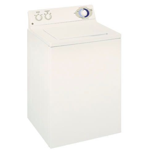
                                       GE washer model ​WCSR2080BCC

Appliance Repair Tips

Unplug the appliance and turn off its water supply before starting any repairs. Safety goggles and gloves are needed to protect hands and eyes from sharp objects as you remove and replace damaged components.

The Tub-to-Pump Hose

When the washer tub drains, water travels through the tub-to-pump hose. As an appliance ages, the hose can crack, causing water to leak out. Replacing the damaged tub-to-pump hose is not complicated and should only take a little over an hour.

How to Replace the Tub-to-Pump Hose in Your GE Washer

  1. To gain access to the tub-to-pump hose, remove the washer’s front panel. At the left and right corners of the washer, insert a putty knife in between the main top and the front panel. Slide the putty knife toward the center of the appliance. When the knife makes contact with a locking tab, push down to release the mechanism. Once both tabs are disengaged, tip the front panel back, and take it off the washer.
  2. The tub-to-pump hose can be found in the washer’s lower right corner. Before disconnecting it, place a towel in the area underneath the component. Use pliers to loosen and slide the lower clamp up the hose. Then, pull the bottom half of the hose off the drain pump. A small amount of water is likely to come out of the hose, which should be caught with the towel. Next, use a nut driver to unthread the screw securing the upper hose clamp. Once the clamp is loose, disconnect the top end of the hose from the outer tub. Now the damaged tub-to-pump hose can be removed from the washing machine.
  3. Before discarding the old hose, take the top and bottom clamps off the part so they can be attached to the new drain hose.
  4. Slide the old clamps onto the new tub-to-pump hose. With both clamps attached, go to the washer and install the top end of the hose to the outer tub. Secure the connection by tightening the clamp screw with the nut driver. Then, attach the lower end of the hose to the pump. Using pliers, slide the clamp down the hose to secure the link between the drain pump and the hose.
  5. To complete the repair, reinstall the washer’s front panel. After the appliance is reassembled, plug it in and turn on its water supply. Test the new tub-to-pump hose by washing a load of laundry. If the washer doesn’t leak, the new component resolved the issue.

The Drain Pump

If the washer is leaking during the wash cycle or the drain cycle, there is a good chance it has a faulty drain pump. The drain pump pulls water from the washer tub and pushes it out of the appliance through the outlet hose. If the pump is cracked, water will leak onto the laundry room floor.

How to Replace GE Washer Drain Pump

  1. Start repair by taking off the washer’s front panel. In between the appliance’s main top and front panel are two locking tabs: one is near the right corner and the other is near the left corner. To disengage the tabs, slide a putty knife between the panels and press down. After both tabs are released, lift the front panel up and off the washer.
  2. Locate the drain pump and place a towel underneath it to catch any water that may come out during the repair. Next, disconnect the wire harnesses running to the drain pump. Then, use pliers to loosen the clamps securing the outlet and inlet drain hoses to the pump, and pull the hoses off the drain pump valves. With a socket wrench, unthread the screws holding the pump’s mounting plate to the bottom of the washer. Once the screws are removed, pull the damaged drain pump out of the appliance.
  3. To install the new drain pump, attach its mounting plate to the bottom of the washer. After the drain pump is in place, reconnect the wire harnesses and the outlet and inlet drain hoses. Make sure the hoses are attached properly and the clamps are securely linking the hoses to the pump valves.
  4. With the new drain hose successfully connected, reinstall the washer’s front panel. Once the panel is reattached, plug the appliance back in and turn on the water supply. To ensure the repair worked, test out the machine by running a wash cycle.


Special thanks to Fred’s Appliance Academy for this helpful tip!

Encompass Holiday Hours

Please note all Encompass locations will close at 3:00 pm Eastern on Monday, Dec. 31. We will be closed on Jan. 1, 2019. This timing coincides with the last pick ups for the day by both UPS and FedEx:

  • UPS will only pick up Air and International orders on Dec. 31. No ground packages will be picked up or delivered.
  • FedEx will pick up Ground and Air packages on Dec. 31, although only Air packages will be transported. All Ground packages will remain at the terminal until Wednesday, Jan. 2.

On behalf of the entire Encompass team, we wish you and your family a wonderful, joyous holiday!

CE Tech Tips — December 2018

**NOTICE**
Due to the danger and complexity of electronic equipment repair, the following technical tip is intended for professional reference only. Please refer to manufacturer’s recommendations as Encompass does not guarantee the accuracy, reliability or safety of this information. 


Panasonic TV,  TCL42E3
Reason for Service:  Won’t come on, one blink error code
Solution: LEDs were coming on, but only for a second.  Replaced LED driver board.

Toshiba TV,  50H72
Reason for Service: Dead & F470 blown
Solution:  Replacing C884 and F470 fixed the set.

LG TV,  37LP1DUA
Reason for Service: Immediate shutdown after powering on
Solution: IC851 in the power supply was bad.  SM #L6910.

Audiovox TV VE705, 7” LCD
Reason for Service: Dead set, no standby
Solution: Found bad cap in power supply, 1000uF/25V.

Hitachi TV,  60SDX88B
Reason for Service: Black rectangular bar floating up screen on all inputs; audio low and set may shut down.
Solution: Found and replaced open cap, CN06,  10uF/50V.

Westinghouse TV, TX-47F430S
Reason for Service: Set won’t turn on
Solution: Found bad capacitor on main board.  TC51,  470uF/16V

Samsung TV,  PN50A550
Reason for Service: Relays click when set plugged in. After few seconds, power shuts off then back on.
Solution: Replaced C102, 47uF/6.3V.  If still not working, replace DC to DC converter, MP2363DN.

Zenith TV,  9-1998 module
Reason for Service:  There was vertical foldover when brightness and contrast turned up.
Solution: Found and replaced leaky cap,  CX3233,  47uF/160V

How to Troubleshoot Non-Heating Whirlpool Oven

**NOTICE**
Due to the danger and complexity of electronic equipment repair, the following technical tip is intended for professional reference only. Please refer to manufacturer’s recommendations as Encompass does not guarantee the accuracy, reliability or safety of this information. 

If it wasn’t for your Whirlpool oven model WFG320M0BW, your family wouldn’t enjoy all those delicious meals you make for them. Unfortunately, the more use your oven gets, the more wear and tear its components endure. One of the most common
oven malfunctions failing to heat. Diagnosing and fixing an oven that is producing little to no heat is a repair you can probably handle on your own. To help you troubleshoot a non-heating oven, here’s a list of components known to affect heating:

Safety Reminder: Always unplug an appliance before starting a repair. If you’re working with a gas oven, turn off the gas supply valve. Always wear work gloves and safety goggles when fixing a malfunctioning appliance.

Check Your Gas Supply
Before inspecting any other components in your oven, test the appliance gas supply. If your oven isn’t receiving gas, it won’t be able to heat up. To check the gas supply, simply turn on a cooktop burner. If the burner ignites, gas is entering the appliance. If the burner stays unlit, pull the range away from the wall to ensure the gas cutoff valve is open. Once you confirm the valve is in the open position, contact your gas provider to find out why no gas is coming from the supply valve.

Oven Igniter
The oven igniter should produce enough heat to open the gas valve and ignite gas entering the appliance. Over time, the igniter can weaken, meaning it will take longer to heat up. If the igniter glows for over a minute without a flame igniting, it’s no longer functioning properly.

How to Replace the Oven Igniter in Your Whirlpool Oven

  1. Start the repair by removing the lower access panel from the back of the range. Once the panel is off, pull apart the igniter and gas safety valve wire harnesses.
  2. Open the oven door, and take out the racks. Remove the oven’s lower access panel by lifting the back up first, and then sliding the panel toward the front of the oven.
  3. The oven igniter is located on the side of the burner tube, which runs through the middle of the oven cavity. To remove the faulty oven igniter, detach the burner tube and take it out. To do so, simply unthread the mounting screws securing it to the inside of the oven. Once the burner tube is free, pull it and the oven igniter out of the oven cavity.
  4. Place the burner tube on a flat solid surface, and remove the screws securing the defective oven igniter to the burner tube.
  5. Align the new oven igniter with the mounting bracket on the burner tube. Secure the igniter with screws.
  6. Go back to the range and reinstall the burner tube. Push the igniter wires through the opening on the oven’s rear wall. Reinsert the oven’s lower access panel, and place the oven racks back in the appliance.
  7. At the back of the appliance, reconnect the igniter wire harness with the gas safety valve harness. Replace the lower access panel and secure it with the four screws removed earlier.
  8. Plug the appliance back in, and turn on the gas supply valve. Set oven to preheat and wait for it to warm up to determine if the new oven igniter solved the heating problem.

The Oven Sensor Assembly
The oven sensor and the oven control board work as a team to measure and regulate oven temperature. The sensor detects the temperature inside the oven cavity. If it is defective, the oven will not heat at all or the sensor accuracy will be off by 50 degrees or more.

How to Replace Whirlpool Oven Sensor 

  1. At the back of the oven, disconnect the sensor wire harness. Unthread the two screws securing the oven sensor to the range’s rear panel.
  2. Once the screws are removed, slide the sensor out of the opening at the back of the oven.
  3. Insert the new oven sensor into the hole in the rear panel. Replace the mounting screws to hold the sensor in place. Finally, reconnect the wire harness.
  4. Plug in the range, and turn the gas back on. Test the new sensor by turning the oven on and measuring the temperature inside with an oven thermometer.

Other Contributing Components to Non-Heating Oven Malfunction
The Oven Control Board, as mentioned above, works in conjunction with the oven sensor. While the sensor is more likely to malfunction, the control board can also end up failing. If this happens, the component may inaccurately read the temperature sent from the oven sensor, which can lead to the oven not heating at all or the temperature being significantly wrong. Replacing the defective control board is your best option.

The Gas Safety Valve regulates when gas is and isn’t released into the oven. If the component is working properly, the safety valve will open when the oven igniter begins to glow white hot. A malfunctioning gas safety valve won’t allow gas into the oven, even after the igniter is hot enough to ignite the gas. While a defective safety valve can happen, it is a rare occurrence, meaning you should rule out more common malfunctions first. However, if you do discover the gas safety valve is causing a
non-heating oven, replacing the component is the only way to fix the problem.

Special thanks to Fred’s Appliance Academy for this helpful tip!

CE Tech Tips — November 2018

**NOTICE**
Due to the danger and complexity of electronic equipment repair, the following technical tip is intended for professional reference only. Please refer to manufacturer’s recommendations as Encompass does not guarantee the accuracy, reliability or safety of this information. 

Akai TV, PDP4294
Reason for Service: Set won’t start; relay clicks with 6 blinks
Solution: Replaced C523 & C524 in power supply. 0.22uF/400V 

Samsung TV, HL61A650C1FXZA
Reason for Service: Set shuts down after being on for short time
Solution: Found lots of dust on fans and fan intake for the fans.  Cleaning enabled set to operate normally again.

Samsung TV, UN55C6900VFXZA
Reason for Service:
Dead, no blinking codes
Solution: Replaced ICB801 and zener ZDB802.

Sony TV, KDL46HX729
Reason for Service: Dead
Solution:  Replaced power supply, 1-474-306-11  G5 board.

Toshiba TV,  50H72
Reason for Service:  White screen with lines in it
Solution: Found cold solder on the black wire that feeds the convergence IC’s.
Repaired solder and replaced fuse F850 (5A) and both STK392-110 IC’s.

Vizio TV,  VO370M
Reason for Service: Remote not working
Solution: Found CR2 leaky on remote board. 

Westinghouse TV, TX42F430S
Reason for Service: Set seems to come on, (power light on) but no backlights
Solution: Found bad cap on main board: TC51,  470uF/16V. 

Zenith TV, A27A76R  (module  9-1998)
Reason for Service: Picture is too red, green or blue
Solution: Found leaky Q2205 on main and bad solder on Q5102 on CRT board.

Zenith TV, A27A76R
Reason for Service: Vert rolling and shrinking when cold.
Solution: Replaced CX2105, 220 at 35V.

Encompass Now Authorized Supplier of Samsung Warranty Appliance Service Parts

Lawrenceville, Ga., November 1, 2018 – Encompass Supply Chain Solutions, Inc., a leading provider of Parts Distribution, 3PL and 4PL solutions for a diverse range of finished goods and replacement parts, today announced it is now authorized to supply parts for warranty repairs of Samsung home appliances.

Under an expanded agreement with Samsung Electronics America, Inc. – a global name in leading-edge appliance, electronics, audio, printing products and more – Encompass may distribute service parts for use in Samsung warranty appliance product repairs.

Marking its 65th year of business in 2018, Encompass maintains one of the largest Samsung parts inventories in the country through long-term support of the acclaimed brand for non- and extended warranty repairs of its comprehensive product lines.

“Encompass has supplied Samsung parts for the past 20 years and is thrilled to be strengthening our partnership into warranty parts supply,” said Encompass President and CEO Robert Coolidge. “With this added authorization, Samsung’s service network can rely on Encompass for all their service parts needs.”

Encompass supports service providers from strategically-located facilities in Florida, Georgia and Nevada. Parts – along with helpful resources such as exploded views and 360-degree photographs – are available from its user-friendly, feature-rich website encompass.com. The website was recently modified to accept Samsung claim numbers to expedite warranty orders.

Encompass Senior Vice President of Sales and Marketing Joe Hurley said the supplier expects to increase home appliance parts availability for Samsung’s authorized service network, ensuring enhanced product experience for end users.

“Standing behind their products with strong, consistent aftersales support is instrumental in building and maintaining manufacturer brand loyalty,” said Hurley. “Encompass is fully committed to delivering first-class customer service for Samsung consumers and servicers alike.”

In addition to reinforcing its position as a one-stop supplier through warranty authorizations, Encompass is heavily focused on continually adding original parts for repair of a wide variety of products throughout the home.

 About Encompass Supply Chain Solutions, Inc.

Encompass is a market leader in forward and reverse supply chain management and high-tech repair services for a diverse and expanding range of consumer electronics, computer, major appliances and imaging products.  Encompass provides end-to-end solutions for OEMs, retailers, independent dealers, third-party administrators and consumers.

Encompass manages all stages of the product lifecycle, including finished goods and replacement parts logistics, board repair and product refurbishment services, returns management, asset value recovery and eco-friendly disposal. For more information, please visit solutions.encompass.com and follow us on LinkedIn, Facebook and Twitter.

Inner Workings of Microwaves

**NOTICE**
Due to the danger and complexity of electronic equipment repair, the following technical tip is intended for professional reference only. Please refer to manufacturer’s recommendations as Encompass does not guarantee the accuracy, reliability or safety of this information. 

Although microwave ovens vary in design, they are virtually all similar in function. Most models are equipped with preset cooking times, programmed according to the basic popularity of certain food items, such as popcorn. Microwaves also have power level setting and timing options for food items not included in the pre-set modules.

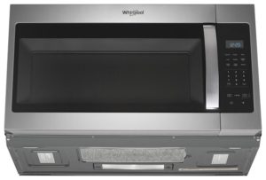
After the desired cooking setting has been chosen and the start button pressed, the control board sends 120 volts of electricity traveling through a series of components inside your microwave and converts it into high-powered radio waves that cook your food. Once the radio waves are inside the cooking area, they penetrate the food from the outside in causing moisture in the food to vibrate intensely. It is this vibration that generates the heat that cooks the food.

Models equipped with a motorized turntable, rotate food so that radio waves can cook the food uniformly. For more, watch this  5-minute video for a deeper understanding of how a microwave oven works. Here are some tips to deal with operational issues:

How to Remove and Replace the Magnetron in a Microwave Not Heating
If your microwave fails to warm or cook your food, it’s possible that the magnetron will need to be replaced. Due to the electrical danger involved, it’s recommended that this service be performed by a professional appliance repair company; here are the repair basics:

Tools Needed

  • Two insulated screwdrivers
  • Needle nose pliers
  • # 20 Torx screwdriver
  • Phillips screwdriver

The following procedure is for a Whirlpool microwave that sits above the range. Servicing will take some time and patience to complete. Several screws must be removed to access the magnetron. Place the screws in a container to avoid misplacement and then:

  • Remove turntable and set aside.
  • Using Phillips bit with electrical drill, dismount microwave by removing two screws that hold it to kitchen cabinet.
  • Tilt microwave toward you at about 45-degree angle and lift it off rear bracket that holds it in place on kitchen wall.
  • Remove grill and set aside.
  • Flip microwave on its back and remove eight Phillips-style screws. When completed, flip microwave back to its original position.
  • Remove 10 Phillips screws that hold microwave wrap in place. Remove rear cover and set aside.
  • Now remove eight more screws from top of microwave cover.
  • Don’t forget to remove two screws that hold blower cover in place. Remove cover and set aside.
  • With all exterior screws removed, you should be able to grab sides of cover and gently pull toward yourself, lift it from its place and set aside.
  • Remove panel that protects diode and capacitor.
  • Since capacitor retains residual voltage that could result in serious shock, you are going to short out remaining electricity.
  • Place metal end of one insulated screwdriver on one capacitor terminal and place  other insulated screwdriver on other tab. Cross screwdrivers and hold them together, metal to metal. You should hear pop or see spark discharging any
    remaining voltage in capacitor. To be safe, perform this task twice. After discharging residual voltage, and with microwave unplugged, it should be safe to proceed with removing magnetron.
  • Access magnetron by removing three Phillips type screws that hold waveguide to rear panel. The waveguide is a plastic tube-like guide that directs radio waves to inside of microwave.
  • Before removing waveguide, remove power cord ground wire from rear panel.
  • Remove power cord by sliding it out of its guide and set aside to keep out of the way.
  • Remove last screw holding waveguide in place and carefully manipulate waveguide from its place and set aside. There is one more part to remove before you can access magnetron.
  • Remove magnetron thermostat, which is held in place with two Phillips screws. Gently pull thermostat away from magnetron.
  • Use needle nose pliers to disconnect locking tabs from magnetron. Pinch tabs inward until you feel release and pull wire away from  tab. It does not matter in what order these wire tabs are reconnected to new magnetron; they are just
    completing a circuit.
  • Use #20 Torx screwdriver to remove four screws that hold magnetron in position. Lift old magnetron from its location and set aside. You are now ready to install new magnetron and return microwave to its previous state. You are going to pretty much do everything in reverse order, but following is a quick go-to guide that will help ensure you reassemble all parts and screws to their previous locations. It is no good to finally get the microwave back together only to discover the blower fan cover was not reinstalled, or worst yet, the waveguide.
    â—Ź Install the new magnetron (two torx screws).
    â—Ź Reconnect wire tabs.
    â—Ź Return magnetron thermostat to proper location (two Phillips screws).
    â—Ź Reinstall waveguide cover (three Phillips screws).
    â—Ź Slide power cord into its guide.
    â—Ź Reconnect power cord ground wire to rear panel.
    â—Ź Reinstall high voltage protective cover (two Phillips screws).
    â—Ź Reinstall cover, and don’t forget to feed power cord through fan opening.
    â—Ź Ensure cover is flush with panel by placing slide into panel and ensure no gaps exist on either side.
    â—Ź Reinstall back screws first to keep cover in place.
    â—Ź Replace fan cover, making sure to slide tabs into designated slots.
    â—Ź Reinstall all screws in top panels.
    â—Ź Flip microwave on its back and reinstall the eight Phillips screws.
    ● Flip upright and replace grill, ensuring tabs line up to designated slots. Once grill is in place, use two Phillips screws to  secure. Do not over tighten any screw used to hold plastic part in place as plastic could crack or break.
    â—Ź Enlist help to hold and balance microwave as you line it up with bracket that holds unit to wall.
    â—Ź Feed power cord through designated hole in kitchen cabinet.
    ● Reinstall the two Phillips screws that anchor top of microwave to bottom of  kitchen cabinet.

Special thanks to Fred’s Appliance Academy for this helpful tip!

CE Tech Tips — September 2018

**NOTICE**
Due to the danger and complexity of electronic equipment repair, the following technical tip is intended for professional reference only. Please refer to manufacturer’s recommendations as Encompass does not guarantee the accuracy, reliability or safety of this information. 

LG TV,  47LH41UE
Reason for Service:  Dead
Solution: Replaced D601 diode pack. Check insulation for diode pack to heat sink and screw insulator.

RCA TV, D52W20,  (ITC222)
Reason for Service: Picture normal with bright set low, but distorts and stretches when brightness is adjusted up.
Solution: Check DI106 and DI032.

Samsung TV, HL61A650C1FXZA
Reason for Service: Set won’t come on.  Power light cycles on, then off, on then off, etc.
Solution: Replaced ballast cap C20, and two open caps in the power supply.  C801S & C802S.

Samsung TV, HL72A650C1FXZA
Reason for Service: At turn on, lamp flickers then set turns off.
Solution: This was caused by two bad caps in main power supply.  C802 & C810; both 470 at 200V.

Samsung TV,  PN43E450A
Reason for Service:  Set won’t start or shuts down intermittently.
Solution:  Pin 1 of CN801 not fully seated in connector.  Reseating pin fixed the set.

Sharp TV, LC46LE830U
Reason for Service: Shutdown, error was 2 slow then 5 fast blinks.
Solution: Replaced the power board: RUNTKA790WJQZ. 

Sony TV, KDL32L504
Reason for Service:  Dead, maybe lightning
Solution: Replaced IC6102,  #670880101

Toshiba TV,  46XV648U
Reason for Service:  Dead
Solution:  In power supply, found R850 bad.  1.8 ohm, 5W.  Also replaced relays SR80 & SR81.

CE Tech Tips — August 2018

**NOTICE**
Due to the danger and complexity of electronic equipment repair, the following technical tip is intended for professional reference only. Please refer to manufacturer’s recommendations as Encompass does not guarantee the accuracy, reliability or safety of this information. 

Samsung TV, LN37A550P3F
Reason for Service:  Normal picture goes to white screen in about a minute
Solution: There’s a bad chip on the T-Con; use freeze spray to find and verify.

Samsung TV,  PN60E7000
Reason for Service:  Might be dead, or comes on for a short time, then turns off
Solution:  Look for bad solder on the FETs. Clean and resolder.

Sony TV,  KDL32S20L
Reason for Service:  Backlight comes on for short time then goes off; 4 blink error
Solution: Look for bad ccfl tubes, shorted FET drivers and/or defective output transformer.

Sony TV,  KDS55A2000
Reason for Service:  Shutdown with 4 blink error
Solution:  Remove back and look for dust in exhaust fan. Cleaning should fix the set.

Panasonic TV,  TCP50U50
Reason for Service:  Shutdown, 8 blink error.
Solution:  Found Q051 shorted on SS Board; DG3D3020CVLW.  Use screw kit also: XYN3-F6FJ-18PK.

Toshiba TV, 46SL412U
Reason for Service: Power LED flashes at turn on, but set won’t start
Solution: Found bad Q30 on main board; replacing fixed set.

Vizio TV, VX37LHDTV10A
Reason for Service: No backlight. Emblem turns amber when set plugged in, then turns white when set turned on. Cannot turn set off without unplugging.
Solution: Power supply voltages okay. Main regulator U7 was bad.  Replacing it fixed set.

Westinghouse TV,  TX42F430S
Reason for Service:  Dead, has amber standby
Solution:  Found bad cap, TC51.  470uF/16V.  Replacing fixed set.


Dryer Troubleshooting

**NOTICE**
Due to the danger and complexity of electronic equipment repair, the following technical tip is intended for professional reference only. Please refer to manufacturer’s recommendations as Encompass does not guarantee the accuracy, reliability or safety of this information. 

Back in 2009, John La Grou, an electronics innovator, gave a Ted Talk on how to prevent home and office fires with a “smarter type of electrical outlet.” John wanted to look his best. The night before he was to give his Ted Talk, he did a load of laundry. After the wash cycle completed, he threw the load in the dryer and went to bed. Upon rising, he went to the dryer to find that his laundry was still as damp as when he had pulled it from the washing machine.

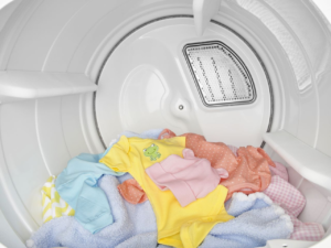
He only had a few hours before his presentation. In dismay, he Googled the keywords “dryer won’t heat up.” Lacking the time to do any troubleshooting on his own, he called a reputable appliance repair company and was greeted by a kind and patient customer service representative who asked a few basic questions. The inquiries seemed simple, but were
intended to eliminate oversights that could happen to anyone — especially when your mind is overloaded.

When troubleshooting, it’s best to start with the most obvious and simple repairs first, working toward the more uncommon and difficult repairs. The customer service rep wanted to know:

  • Does the dryer run at all?
  • If the dryer does not run, have you looked to see if the dryer is plugged in?
  • If the dryer is plugged in but still does not run, have you checked the circuit breaker switch? There may have been a circuitry overload that tripped a breaker switch.
  • If the dryer is not on a circuit breaker system, have you checked for a blown fuse?
  • Have you checked the selector switch to see if you set it to air dry only?
  • When you open the dryer door, do you smell mold and mildew? This could indicate poor drainage or some type of moisture leak from previous drying sessions and definitely increases the chances of an electrical short. If the washer is leaking, some of that water could have invaded the dryer and become the source of moisture.

Asking these questions may seem redundant, but could save the expense of an unnecessary service call. There are a few reasons for a dryer to not heat; this article focuses on two.

Tools Needed

  • Multi-meter
  • 5/16th nut driver
  • Flathead screwdriver

The multimeter is the most important tool in an appliance repair toolkit. Give particular consideration on checking for continuity. In reference to electrical components, continuity is simply the unbroken flow of electricity from its power source and distributed through the appliance components.

A break in continuity in any part of the electrical system would indicate that electrical current is not flowing to that component. The good news is that if you find a break in continuity, you will usually have found the part that needs to be repaired or replaced.

Unplug the dryer before beginning any work. Be careful while you work around sharp edges and delicate components. You don’t want to cut yourself or damage another component.

Testing the Thermostat for Continuity
The high limit thermostat is actuated by temperature change. It is located behind the back panel and is attached to the heating element. The thermostat must be removed (see below) and tested at room temperature. Testing for continuity will determine if there is an unbroken flow of current. The following guide is for an analog multimeter:

  • Dial the ohms resistance to the smallest possible setting.
  • Calibrate the multimeter by touching the probes together and adjust the display needle to zero.
  • Next, place a probe on either of the thermostat terminals and the other probe on the other thermostat terminal
  • If the multimeter reads zero ohms of resistance, the thermostat has continuity.
  • If the multimeter display needle does not move or change, there is no continuity and the thermostat should be replaced.

Thermostats should show continuity at room temperature and should shut off when heated up. If it doesn’t turn off when heated, the dryer could overheat and increase the chance of a home fire. If the thermostat didn’t test well for continuity, replace it. It’s an inexpensive repair and shouldn’t take longer than 15 minutes to complete.

How to Remove and Replace the Thermostat on a Whirlpool dryer

  • The thermostat is attached to the heating element located behind the back panel.
  • Remove the back panel.
  • Disconnect the wire from the old high-limit thermostat.
  • Detach the thermostat from the heating element terminal – test for continuity (see above).
  • If the thermostat failed, replace it.
  • Position the new thermostat and secure with two screws.
  • Reconnect the wire to the top terminal.
  • Use the wire that came with the thermostat replacement package and connects the thermostat to the heating element.

The thermostat is designed to turn off at high temperature. If it doesn’t shut off when heated, the dryer itself could overheat, increasing the chance of a home fire. This is one reason to not throw your clothes in the dryer and leave the house. Never leave a dryer running while you’re not at home.

Testing the Thermal Fuse for Continuity

  • With a multimeter, set the ohms resistance to the smallest possible setting.
  • Calibrate the multimeter by touching the probes together and adjust the display needle to zero.
  • Next, place a probe on the thermal fuse terminal and the other probe on the other terminal.
  • If the multimeter reads zero ohms of resistance, the thermal fuse has continuity.
  • If the multimeter display needle does not move or change, there is no continuity and the thermal fuse should be replaced.

You won’t be able to determine if a thermal fuse has failed by simply looking at it. It must be removed and tested for continuity.

How to Remove and Replace the Thermal Fuse

  • Disconnect the wires to the old thermal fuse, remove the screw that holds the fuse in
    place, and remove the old thermal fuse.
  • Next, install the new thermal fuse with the mounting screw.
  • Reconnect the wires.
  • Replace the back panel.
  • Plug the dryer back in to make sure it’s functioning properly.

Oftentimes a failed thermal fuse is caused by a clogged venting system. Ensure the venting system is free of lint and any other material that may have inadvertently become lodged inside. It is recommended that you check the venting system after you change the thermal fuse.

To inspect the dryer vents, turn the dryer on and inspect the vent flap to see if it opens when air is being pushed through the system. If it opens, you’re good to go. If not, it means something is preventing air flow to escape. Dryer venting systems should be inspected regularly.

Special thanks to Fred’s Appliance Academy for this helpful tips!