**NOTICE**
Due to the danger and complexity of electronic equipment repair, the following technical tip is intended for professional reference only. Please refer to manufacturer’s recommendations as Encompass does not guarantee the accuracy, reliability or safety of this information.
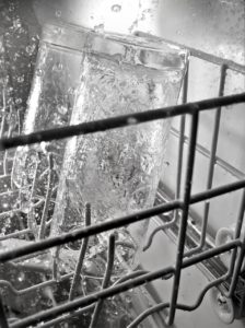
Many factors can cause dishwashers to leak. But if a leak occurs near the bottom of a dishwasher and the water pressure is low during the wash cycle, it likely needs new impellers.
To make the repair, order a drain and wash impeller kit, which is part #675806 for Whirlpool, Maytag and other common dishwasher brands. Then, follow these steps to install the new parts:
1. Unplug dishwasher and turn off water supply.
When repairing a major appliance, the first step is always disconnecting the unit from its power supply. Even though this replacement procedure doesn’t directly involve electrical components, it’s safer to unplug the appliance and turn off the water supply. This reduces the risk of leaks and water damage during the repair.
 2. Access the pump.
Open the dishwasher door, remove the lower rack and set aside. Loosen the spray arm nut counterclockwise and set aside. Remove the whole lower spray arm. Next, take out the bearing — these are the loose parts that need to be set aside before you start dismantling the base of the machine.
3. Uninstall the old drain and wash impellers.
Remove the eight screws securing the pump to the base. Pick up the pump, and pull it free from the hose. Use a wrench to hold the impeller in place, then remove the screw in the middle of the impeller. Without the wrench, the part will spin in place. Set the screw aside, and lift the impeller free. Uninstall the filter assembly, and pull it out. The filter has a gasket around the top. If the part came with a replacement seal, remove the old one and set it aside. Clean the filter of hard water deposits and grime to ensure the new seal sets into place properly.
Lift the chopper and spring assembly away from the shaft. Then, unscrew and remove the cover. Now the drain impeller is completely accessible. Pry it free from the central shaft. If the drain impeller is secured too firmly in place from years of use, carefully chisel the part and break it free. Discard all of these parts.
Next, pry the seal away from the bottom of the shaft. Clean the area with a cloth or vacuum, especially if you had to break the impeller into parts. Make sure the white balls in the bottom compartment don’t get lost or removed. If the central shaft is rusty
or dirty, now is also the perfect time to clean or file it into better shape.
4. Install the new drain and wash impeller kit, and reassemble the machine.
These steps work in reverse from the kit removal in the previous step. The kit involves many parts that look similar, so be sure to refer to the installation diagram as needed to use the correct parts during installation. Before starting, you may want to keep the drain and wash impeller kit parts in a plastic container so they stay separate from the other parts you removed from
the machine. This can also help simplify the reassembly process because the drain and wash impellers are separated by older parts that will be reinstalled.
Start with the seal assembly. Slide the seal over the shaft, and make sure the seal is tightly aligned and flat with the base. Next, align the drain impeller hole with the pattern on the shaft. Slide it down against the seal, and place the cover into position. Secure it with the screw removed previously.
5. Install the spring and chopper.
Pick up the spring and chopper parts. Slide the long end of the spring into the edge of the chopper so the middle of the spring and the hole in the chopper align. Then, slide it over the shaft with the spring side down. Rotate the assembly clockwise until the start of the spring interlocks with the top of the impeller.
6. Reinstall the filter assembly.
Find the side of the filter assembly that has a flat section along the top. This is where the wide hose connects to the drain, so orient this section to the back of the machine when you put the filter assembly over the shaft. Retighten the four screws that secure the filter assembly in place.
7. Install the wash impeller assembly.
Line the hole in the middle of the wash impeller with the flat grooves in the shaft. Slide the wash assembly flush against the top of the filter assembly. Then, hold the impeller in place with your wrench again. This enables you to re-tighten the central screw.
8. Make sure the screw is firmly tightened.
This screw is what applies the pressure against the water seal below. Test the wash impeller to make sure you can manually rotate it without any drag or unexpected friction. Put the new seal in the filter’s housing. The ring should slide into the groove without much stretching or tension.
9. Reinstall the pump.
Firmly insert the pump’s arm into the supply tube. Then, shift the assembly on top of the filter assembly. Once it’s in place over the central shaft, re-secure it with the eight screws. Slide the split bearing you removed earlier on top of the central shaft. Next, put the lower spray arm assembly on top of it. Make sure it’s level before you tighten the spray arm nut. Once the assembly is
secured, make sure the spray arm can rotate without drag or wobbling.
10. Put the lower rack back into the machine and close your dishwasher.
This repair procedure has a lot of moving parts, but it doesn’t require extensive experience or specialty tools. All you need is the replacement parts and enough space to stay comfortably organized.
Special thanks to Fred’s Appliance Academy for this helpful tip!


 If the power supply, heating elements, thermostat, fuse and heat sensor are operating correctly, it’s a good possibility that the main control board is malfunctioning and will need to be replaced. Since the thermal fuse is functioning properly, this symptom should convey that the control board is getting power but is incapable of operating the oven.
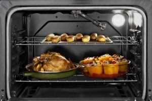 Oven Igniter
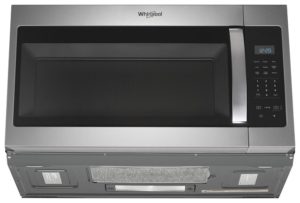 After the desired cooking setting has been chosen and the start button pressed, the control board sends 120 volts of electricity traveling through a series of components inside your microwave and converts it into high-powered radio waves that cook your food. Once the radio waves are inside the cooking area, they penetrate the food from the outside in causing moisture in the food to vibrate intensely. It is this vibration that generates the heat that cooks the food.