Tech Tips

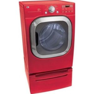
LG Dryer Faulty Gas Burner Valve Assembly

**NOTICE**
Due to the danger and complexity of electronic equipment repair, the following technical tip is intended for professional reference only. Please refer to manufacturer’s recommendations as Encompass does not guarantee the accuracy, reliability or safety of this information. 

How to Replace a Faulty Gas Burner Valve Assembly in a LG Dryer

If clothes are still wet after completing the dry cycle in LG dryer model DLG2602R, it is likely due to lack of heat. This is a common dryer issue that could be caused by numerous possible malfunctions.

Once determining there are no issues with the high limit thermostat, flame sensor, thermistor and ignitor, consider examining the gas burner valve assembly, which supplies gas to the dryer burner. A malfunctioning valve assembly won’t administer gas, which means the dryer won’t heat.

Before starting any dryer repairs, unplug it from the wall and turn off the gas supply valve. Never attempt a repair without wearing proper safety gear, such as work gloves and goggles. As with all technically difficult and potentially dangerous repair, this repair is best left to a
specialist.

Steps to Replacing Gas Burner Valve Assembly

  1. Pull LG dryer forward and away from laundry room wall. On the back of the appliance, unthread screws that secure the top panel to  dryer. Once screws are out, pull panel toward you, and lift it up and off dryer.
  2. Now, disassemble the control panel. (Before disconnecting wires, it’s a good idea to take a photo of all wire connections to assist in easily reconnecting them during reassembly.) Start detaching the wire harnesses from the back of the board. Once all wires are disconnected, take out the screws that hold the control board console to the dryer, and then pull console off front of dryer.
  3. With control board removed, disconnect the door switch located near the top center of the door frame. Next, open dryer door and
    unthread screws that hold front panel to lint screen housing. Once the screws are out, close the door and unthread screws at the top of the front panel. Then, carefully tilt front panel backward, and pull it up and off dryer.
  4. Now, remove control panel bracket off the dryer. First, locate dryer light bulb and disconnect wire harness running to it. Next, locate two wiring retaining clips on the back of the bracket. Take out the wires being held in the retaining clips. Then, remove screws holding the control panel bracket to the front of dryer, and pull bracket off dryer.
  5. Near the bottom of dryer, disconnect wire harness to the moisture sensor. Once the wires are separated, unthread screws that
    secure bulkhead to dryer and carefully lift off.
  6. Reach in between dryer floor and dryer drum to take drive belt off idler pulley and drive motor pulley.
  7. Grab drive belt on top of dryer drum and use to help guide drum out of dryer cabinet.
  8. With drum removed, locate gas burner valve assembly in the cabinet’s lower right hand corner. Disconnect wire harnesses running to valve assembly terminals. With a Phillips screwdriver, unthread screws that secure gas line to burner valve. Once screws are loose, carefully pull gas line off burner valve. Next, take out screws holding valve assembly to mounting bracket, and then take gas burner valve off mounting bracket and out of dryer cabinet.
  9. Before installing new valve, take the orifice off the old gas burner valve and place on new component. Once orifice is securely
    attached to the new gas burner valve assembly, proceed with installation process.
  10. Place gas burner valve assembly on mounting bracket, ensuring screw holes are lined up on bracket with screw holes on the valve
    assembly. Then, replace screws used to secure gas burner valve to mounting bracket. Next, align gas supply tube with burner valve, and insert tube into the valve. Once tube and valve are connected, rethread screws taken out earlier to secure the tube to the valve. To complete installation, reconnect gas burner wire harnesses to valve terminals.
  11. Before putting dryer back together, take a moment to check for any gas leaks. To do so, fill a spray bottle with soapy water, and turn  gas supply valve back on. Then, spray gas burner valve with soapy water. If any bubbles form, a gas leak is present, meaning the connection is not tight enough. At this point, turn off dryer’s gas supply, and try tightening the tube and valve coupling. Once you’ve adjusted the union, turn gas back on, and run gas leak test again. If no bubbles appear, the gas leak should no longer be an issue. If bubbles are still forming, DIY consumers should contact a dryer repair technician to further inspect.
  12. After testing for leaks and none are found, turn off gas running to the dryer, and start reassembling the dryer. Pick up dryer drum and carefully guide it into the dryer cabinet, ensuring the drum back sits on the drum rollers. Then, reach in between the drum and dryer floor to rethread drive belt on idler pulley and drive motor pulley. Make sure belt is installed in zigzag formation.
  13. Retrieve dryer bulkhead, and align with front of dryer. Then, secure part with screws taken out earlier. With bulkhead in place,
    reconnect moisture sensor wire harness, and light bulb wire harness.
  14. Now, reattach control board bracket. Once bracket is in place, pull door switch wire harness to front of dryer through one of the
    openings on the bracket. Then, snap wire into retaining clips on back of the bracket.
  15. Grab dryer front panel and line up with the dryer front. Before laying panel flush, reconnect door switch harness to door switch, and
    finish installing front panel. After adding screws to secure panel, open dryer door, and rethread screws that connect front panel to lint screen housing.
  16. Snap control panel back on dryer, and reattach screws removed earlier. Finish installing control panel by reconnecting wire harnesses that run to the panel back.
  17. Finally, reinstall the dryer’s top panel, plug in the dryer and turn on gas supply valve.

Special thanks to Fred’s Appliance Academy for this helpful tip!


CE Tech Tips — July 2019

**NOTICE**
Due to the danger and complexity of electronic equipment repair, the following technical tip is intended for professional reference only. Please refer to manufacturer’s recommendations as Encompass does not guarantee the accuracy, reliability or safety of this information. 

Hitachi TV, 57UWX20B
Reason for Service: Shuts down.
Solution: Horz output voltage and B+ okay; Horz output transistor collector has distorted waveform.  Replace TH01.

JVC TV, LT32DM20
Reason for Service: Set starts with OSD showing input, then shuts down.
Solution: One of the inverter transformers was bad; replacing it fixed the set. Found it by comparing to other transformers.

Panasonic TV, TH-50PZ80U
Reason for Service:  No picture or OSD after powering on; power light lit.
Solution:  Replacing A board fixed set.

Samsung TV, HLP5085WX/XAA
Reason for Service: Set makes squealing noise when powering on.
Solution: Replaced C540, 1uF/50V SM cap on DMD module.

Samsung TV,  LN-T3753HN
Reason for Service: At turn on, backlight flashes for short time, then no more backlight.
Solution: Replaced inverter.

Sony TV, KDL46W5150
Reason for Service: Set comes on for 10 seconds, then shuts down. Does this three times then gives 10 blink error code.
Solution: Try factory reset.  Turn power on, then immediately press and hold arrow up and press and release power button.

Vizio TV,  VP322HDTV10A
Reason for Service: No audio.
Solution: Replacing SM Q15 fixed problem.

Westinghouse TV, LD-3255VX
Reason for Service: Dead set.
Solution: Replacing U13/14 eeprom fixed set. TW61301-K032A69

How to Replace LG Washer Circulation Pump Motor

**NOTICE**
Due to the danger and complexity of electronic equipment repair, the following technical tip is intended for professional reference only. Please refer to manufacturer’s recommendations as Encompass does not guarantee the accuracy, reliability or safety of this information. 

One of the most important parts of a washing machine is the circulation pump motor. When this part isn’t operating correctly, water isn’t circulating and clothes come out of the wash and rinse cycles still dirty. To replace this part,  order part #EAU61383503.

Following are the installation instructions:
1. Unplug washer and turn off the two water connections.
Please note the first step to any repair is unplugging the appliance. This is especially important when you need to disassemble the machine to reach interior parts. Also, turn off water connections to minimize the risk of a water leak, and pull the appliance away from the wall.

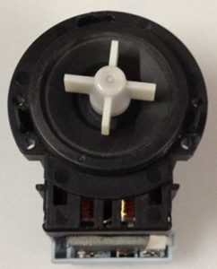
Depending on available space, you may also want to disconnect the water lines and pull the drain line connection out of the wall. During this repair, the machine must be tilted back to reach the circulation pump motor.

2. Disassemble machine to remove front access panel.
Locate pump filter in bottom left corner of machine. Remove door by opening and popping hinges free. Pull black hose out of clip and then remove hose cap. There may be water, so have a towel handy. Next, remove screw that secures pump filter housing in place. Remove housing, then loosen screw beneath that secures front panel to machine frame. Remove the outer boot seal.

Open door, and pry out wire clamp.  Pull outer edge of seal out from edge of front panel. Loosen screw securing door latch mechanism to right side, and then reach past seal around back of front panel to pull mechanism inside machine and out of the way. Then, close door and remove top access panel. At rear of the machine, remove two screws holding top panel to rear brackets. Slide top panel back, lift up and set aside.

Next, remove dispenser drawer at top left corner of control panel. You may have to reach in to depress back tab. Then, remove screw holding housing in place and push inside away from the front panel.

Remove control panel by taking out screw located at right interior side of control panel. Loosen ties holding lengths of wires flush and together against control panel. Unplug the three wire harnesses.

Next, peel the control panel away from front panel starting at top right corner. Once top is loose, tilt it forward to carefully pull wires out of cutout, and set aside. Lean against door and front access panel to hold in place. Then, remove screws along top of front access panel where control panel used to be. Tilt panel forward, lift free of bottom groove, and set aside.

3. Remove existing circulation pump motor.
Locate circulation pump motor in bottom left corner to right of green and cream hoses. Before removing parts, set a box behind the washer and tilt machine back at 45-degree angle for easier access to parts. Don’t pinch hoses and drain lines on the back.

Next, remove two wire harnesses from assembly. Also, remove retaining clip from assembly. Remove three screws that hold pump motor up against housing. The whole part should now come out. Be sure to take a picture of the screws and wires to have a helpful guide when realigning during reassembly.

4. Install new circulation pump motor.
Remove protective shield from part and snap into place around new circulation pump motor. Orient new pump motor so seal fits into housing. Press into place and re-secure all three screws. Next, reattach black and blue wires according to the picture (with black wire on bottom or right port and blue wire on top or left port) and ensure excess lengths of wires are securely held in place in retaining clip.

5. Reassemble washer.
First, pull washer back into standing position so it’s upright. Next, reattach front panel by setting on bottom groove. Tilt it flush with panel front, and lean against it to hold in place while securing top in place with screws.

Now reattach control panel. Set bottom edge against frame and slide wires through the cutout. Tilt panel up flush against frame and snap locking tabs shut. Tighten screw in top right corner inside machine. Then, reattach two wire harnesses on interior sides of machine. Then, slip wires against control panel back and tighten ties to secure wires.

Next, push  dispenser housing back into position in  front opening and secure in place with the two screws. Push drawer back into position and close it.

Set top panel on top of machine, but leave an inch or so hanging over back edge. Slide along rails so it snaps into position under front edge of control panel. Retighten the two screws on back bracket. At front of the machine, push door switch assembly back through cutout on right side of door opening and secure mechanism with the two screws.

Pull seal back into place around the opening. Press edges into groove and run your hand along entire circumference to check for gaps or loose sections. It should snap into place along the lip. Next, install wire clamp into the groove. Orient spring at the bottom and work counterclockwise from there to press into the groove. Once it’s too tight to pull into position by hand, use pliers to stretch the spring and push the extended wire into place around remainder of the circle. Tug on the seal to make sure it’s secure. The clamp and spring should note be visible.

Shut the door and reattach screw in the filter pump cutout to hold everything in place. Then, replace housing and attach with second screw. Reattach drain hose lock to black hose and fold hose back up into retaining clip. Reattach door by snapping hose into position.

Reconnect water lines by retightening them to inlets on the back of the machine and reinsert drain hose to wall connection. Turn on the two water connections, push the washer back into position, and plug washer back in.

Special thanks to Fred’s Appliance Academy for this helpful tip!


CE Tech Tips — May 2019

**NOTICE**
Due to the danger and complexity of electronic equipment repair, the following technical tip is intended for professional reference only. Please refer to manufacturer’s recommendations as Encompass does not guarantee the accuracy, reliability or safety of this information. 

Hitachi TV, 60SX2K
Reason for Service: Loss of color
Solution: Replaced X-501 and C508.

Magnavox 32MF30301B
Reason for Service: Power supply fix
Solution: Replace the following: Q600 & 601, D607, 610 & 640,  R608 & F601.

Panasonic TV, H50PE70U
Reason for Service: Set shuts down when trying to turn on.  Shows 12 blink error code.
Solution: Ohm speakers for a short, unplug it if one is found, then try set again.  Replace shorted speaker.

Philips TV, 40PFL3705D/F7 (Serial # beginning with YA1)
Reason for Service: No picture, but has backlight and audio
Solution: F100 on panel controller board was bad.  Replace with 3.15A SMD.  #PNF10148.

Sanyo TV, DP42647
Reason for Service: Set has black screen, but sound okay
Solution: Found shorted diode on T-Con board: CP4, SR34

Sharp TV, LC-52C6400U
Reason for Service: Dead; error, one long, one short.
Solution: Found bad diode on power board: D7805.  MUR460.

Sony TV, KDL-40V4100
Reason for Service: Picture solarized
Solution: Look for bad AS15 chips on T-Con.

Toshiba TV, XV645U
Reason for Service: Dead set; all fuses okay
Solution: Replacing IC Q880 fixed set.  STRY6456.

Vizio TV, L37HDTV10A
Reason for Service: Set locks up when going to tuner setup on digital input.
Solution: Replaced digital tuner board, #3370-0052-0187.

Accessing and Testing Microwave Door Switches

**NOTICE**
Due to the danger and complexity of electronic equipment repair, the following technical tip is intended for professional reference only. Please refer to manufacturer’s recommendations as Encompass does not guarantee the accuracy, reliability or safety of this information. 

WARNING : Disconnect the microwave from any power source before moving forward.

Microwaves include three switches located behind the control panel: primary, secondary and monitor switch all actuate to keep the microwave from cooking the kitchen while the door is open.

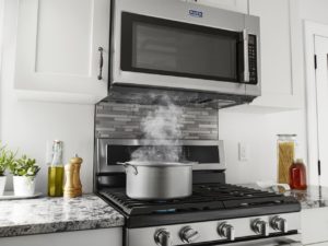
Accessing the Switches

  • Remove the two Phillips screws that hold grill in place on top of microwave. Remove grill and lay aside.
  • Locate and remove the one Phillips screw that holds the control panel in place.
  • Lift up control panel and gently pull toward you. This will provide access to the three switches.
  • Remove all wires from control board. All wires are different from each other and will only fit on the terminal they were designed for.
  • Use needle nose pliers to remove connectors from terminals that can’t be removed by hand. Gently squeeze  connector to release it from the terminal.
  • The last wire to remove is the ground wire, which is connected to the microwave frame. Set control panel aside.
  • Remove  access cover and set aside.

How To Test the Switches

  • Set the multimeter to OHMS to test the three switches.
  • Please note that the primary and secondary switches are tested with the door open. With the door open, place the multimeter leads on the connectors on the primary switch first. When closing the door, the multimeter should produce a beep if the switch is good.
  • Test the secondary switch in the same manner.
  • Test the monitor switch with the door closed. When opening the door, the meter should beep.
  • If appropriate beeps did not sound on any or all three of these switches, replace the switch.

These three switches serve mainly to keep the microwave from operating with the door open. The switches also deliver voltage to the diode and magnetron which heat the microwave. If the switches test positive, this further confirms that magnetron has failed and needs to be replaced.

It’s time to button up the microwave. For most people, this is as far as you may wish to proceed. There is an ever increased chance of suffering a powerful electrical shock from the high voltage capacitor, which retains a residual amount of electricity. It will need to be discharged before the magnetron and high powered diode can be accessed and replaced.

Route the control panel wires back through the appropriate slots in the access cover and reattach the cover to the microwave frame. Reconnect the ground wire first and then reconnect all other wires to their compatible terminals.

Push the control panel back in place and secure with its Phillips screw. With the door open, replace grill cover. Opening the door makes it easier to replace the grill. Secure with its two Phillips screws. Do not over tighten these screws as the grill is made of plastic and it could break or crack.

Special thanks to Fred’s Appliance Academy for this helpful tip!

CE Tech Tips — April 2019

**NOTICE**
Due to the danger and complexity of electronic equipment repair, the following technical tip is intended for professional reference only. Please refer to manufacturer’s recommendations as Encompass does not guarantee the accuracy, reliability or safety of this information. 

Hitachi TV, 53FDX20B
Reason for Service: No picture or OSD, but power light comes on.
Solution:  Replaced C603.

LG TV, 47LM4600UC
Reason for Service: Set seems to turn on, but there is no picture, sound or backlight.
Solution: Found shorted diode on the power board.  D607, MUR460.

Mitsubishi TV, WD65732
Reason for Service: At plug in, green front LED flashes continually. Set won’t start.
Solution: Replacing DM board fixed this set.

Panasonic TV, TC-P55GT30
Reason for Service:  Top half of picture was bad. After a short time, set shuts down.
Solution: Check and replace shorted FETs on SC board. Put star washers under screws and tighten well.

Sears TV, 509.14370, (JVC)
Reason for Service: HV comes up, then set shuts down.
Solution: Replacing the following fixed set: LA7832, D541, R541, 1.8 ohm/2W and C424, 100uF/35V.  Check all solder in vertical area for bad joints.

Sony TV, KDL-46EX720
Reason for Service: Set powers up for just a second, then shuts down with a 4 blink error code.
Solution: Set had bad LED driver board.  Replacing it fixed the set.

Toshiba TV, 50H72
Reason for Service: Diagonal lines on white screen.
Solution: Found and replaced two bad 10uF SM caps in HD module.

Zenith TV B27A76 9-2067 module
Reason for Service: Dead set.
Solution: Found bad cap on unregulated B+ line. CX3407, 300uF/200V.


How to Replace Whirlpool Refrigerator Water Tank and Filter Head Assembly

**NOTICE**
Due to the danger and complexity of electronic equipment repair, the following technical tip is intended for professional reference only. Please refer to manufacturer’s recommendations as Encompass does not guarantee the accuracy, reliability or safety of this information. 

When a leak occurs inside a Whirlpool refrigerator, the water tank and filter head assembly could be at fault. This is the part that connects the water supply line behind the refrigerator to the filter and then to the inlet valve. In an area with hard water, buildup can clog or crack through the tubing. Following are steps to replacing the assembly with part #WP12956202.

1. Unplug refrigerator and turn off water supply
Always be sure to unplug an appliance before starting a repair. Also, because this repair involves replacing part of the water system, turn off the water supply at the local shut-off valve behind the refrigerator. The part being replaced connects directly to the supply line, so disconnect the supply line from the water inlet valve at the base of the refrigerator while you’re behind the appliance.

2. Dismantle refrigerator interior
As the assembly is mostly positioned inside the refrigerator, dismantle some of the inner paneling. To get started, open the doors and remove the right side shelving. (Just pull up to remove the
hooks from the rear brackets and slide them out.)

Next, locate the water filter cover at the top of the refrigerator. Press down the tab to open the covers. Turn the filter counterclockwise and fully remove it. Press the back of the cover panel free of the hinge pin, pull out the whole cover panel and set aside.

Remove the interior access panel in the middle of the right back paneling inside the refrigerator. (This is the panel with the four small holes around the perimeter.) To remove it, insert a flathead screwdriver into each of the holes to depress the locking tabs. For the top two holes, press in toward the opposite hole. For the two lower holes, press the screwdriver down to disengage the tabs. Tilt the panel down and wiggle the bottom free from its mounting tabs and set the panel aside.

Then, remove the upper access panel by inserting the screwdriver into the central hole along the bottom and disengaging the locking tab by pushing it up. Pull the panel out and set aside. The water tank at the back of the refrigerator’s interior is now accessible, as well as the filter head running up the back into the ceiling.

3. Remove old water tank and filter head
The water tank may still contain water. Before removing the old parts, place a towel at the bottom of the refrigerator to catch any leaks.

First, loosen the housing that holds the filter head at the ceiling. Do this by prying open the mounting tabs toward the front of the housing and then rocking the back of the housing free until the housing is supported only by the lines running up to the filter head.

Next, press down the tabs at the top of the blue water inlet valve so you can pull the small tube free from the top. Once it’s free, you can remove the transparent support housing around the tube. Also, pull the water line to the left out of the mounting tabs. Completely separate the housing bracket from around the filter head and set  aside.

Move to the rear of the refrigerator and locate the water inlet tube that was disconnected at the start of the repair. Loosen the screw that holds the tube in place. Push it down and remove the plastic retaining clip from around the tube. Then, remove all the screws holding the lower rear access panel in place. Set the panel aside.

Return to the front of the refrigerator. Start removing the columns of the water tank from the retainer clips. Once they’re all down, carefully pull the water inlet tube into the body of the refrigerator.

4. Install new water tank and filter head
Push inlet tube into the hole at the bottom of the refrigerator. Feed as much of the length through the hole as possible. Next, align the new water tank in the back of the refrigerator so the inlet tube is to the right.

Press the columns of the water tank into the retaining clips until they click and engage. This may have to be done one column at a time to make sure everything fits properly. Return to the rear of the refrigerator. Remove  protective cover at the end of the new inlet tube. Place the old plastic retainer clip on the new tube.

Reattach the rear access panel. Slip the water inlet tube through the bottom cutout and the power cord through the top cutout so nothing gets pinched. Then secure the panel with the screws around the perimeter. Next, attach the water inlet’s retaining clip to the middle of the panel and connect the inlet tube to the water supply line.

Return to the front of the refrigerator. Now install the new filter head attached to the water tank. Take the transport tube support from the old assembly and attach it to the filter head’s inlet tube. Also, attach the filter
housing to the filter head. It should snap into place around the arms at the top of the filter head.

Next, reattach the water tube to the inlet valve. Pry the blue valve slightly forward to make more room. Then, push the tube firmly into the valve. It should go all the way in until reaching the wider portion of the tube. Push  valve back into place.

Fit the longer water line into the groove along the left side of the cavity. Once the tubes are in place, attach the new filter head to the top of the refrigerator. Line up the back of the filter head assembly into the rear of the cavity and then press the cylindrical housing into place. All of the locking tabs should be heard to engage.

5. Reassemble the refrigerator interior.
Start by reattaching the upper inner access panel. Hook the top of the panel over the arms near the filter head assembly. Then, swing the panel until it is flush with the back of the refrigerator. Press firmly into place.

Next, install the lower cover. Slip the bottom of the panel into the groove, and then press the rest of the panel flush with the back of the refrigerator until the locking tabs engage.

Then, install the water filter housing cover: there is a hinge pin on either side of the filter head housing. Slide the matching hole of the hinge at the back of the water filter cover over one arm. Then slightly stretch the other side of the cover to reach around and grab the hinge arm on the other side. Take care not to crack the plastic. Before reattaching the water filter, twist and remove the bypass cap inside the filter head. Twist the water filter into the new filter head clockwise. Then, snap the water filter cover shut. Reinstall the shelves, shut the doors, and
plug in the refrigerator. Be sure to also turn back on the water supply.

Special thanks to Fred’s Appliance Academy for this helpful tip!


CE Tech Tips — March 2019

**NOTICE**
Due to the danger and complexity of electronic equipment repair, the following technical tip is intended for professional reference only. Please refer to manufacturer’s recommendations as Encompass does not guarantee the accuracy, reliability or safety of this information. 

Emerson TV, LC320EM3FA
Reason for Service: Dead set
Solution: Found shorted diode, D633. Replacing fixed set. NTE146A.

Hitachi TV, 53FDX20B
Reason for Service: No pic or onscreen display but power light does come on.
Solution: Found bad C603 and replaced.  

LG TV, 37LP1DUA
Reason for Service: Takes several attempts to turn on set
Solution: Found two bad caps, C114, 10uF/50V and C852, 470uF/10V.

Panasonic TV, TC-37LZ85
Reason for Service:  Dead; no standby 5v or 12V
Solution: Found D7006 leaky in power supply. 15V/1W zenner.

Samsung TV, PN51E550D1FXZA
Reason for Service:  Wi-Fi not working.  Set may cycle on and off.
Solution: Replaced Wi-Fi module. BN59-01148B.

Sceptre TV, X322BV
Reason for Service: Picture was flashing
Solution: Cleaned both ends of LVDS cable and applied Deoxit.

Toshiba TV, 55ZV6T50U
Reason for Service: Dead set
Solution: Replaced relay SR80 and R850, 1.2 ohm/5W.

Vizio TV, VX370E
Reason for Service: Picture solarized
Solution: Replaced AS15-F IC on T-con board.

Zenith TV, H24F36DT
Reason for Service: Remote will not work
Solution: Replacing eeprom, IC6001, fixed set.


How to Disassemble KitchenAid Double Wall Oven

**NOTICE**
Due to the danger and complexity of electronic equipment repair, the following technical tip is intended for professional reference only. Please refer to manufacturer’s recommendations as Encompass does not guarantee the accuracy, reliability or safety of this information. 

The KitchenAid 30-inch double wall convection oven (model #KODE500ESS) is the focus of these tech tips.
Throughout this article are caution alerts signaling a part may be heavy, fragile or comprise unseen sharp objects.
Before beginning any appliance repair project, please remember to always unplug the unit from its power source or shut off the breakers that control the oven.

How to Remove Oven Door

Oven doors are surprisingly heavy, so be prepared when removing it from its hinges.

  • Open oven door all the way.
  • Rotate both door hinge locks toward the oven, releasing door hinges from oven, so it can be removed.
  • Close door to 45-degree angle; grab each side of door; and pull toward you to remove.
  • Lay oven door with handle side down on protective blanket or other soft surface.

How to Access Broil Element and Oven Sensors

  • Be careful to avoid sharp edges when removing and replacing heating elements and oven sensors.
  • Remove all oven racks to gain clear access to rear of oven.
  • Use ¼ inch nut driver to remove screws from bracket that holds  heating element to rear of oven.
  • Remove two screws that hold upper heat shield in place.
  • Carefully pull heating element away from back of oven and disconnect each wire from connector.
  • Ensure heating element wires are completely connected to  accompanying terminals.
  • Realign broil element and shield by inserting oven sensor through large opening in element bracket.
  • Realign smaller front shield and fasten in place with two screws previously removed.
  • Replace rear bracket screws.
  • With ¼ inch nut driver, remove screws that hold oven sensor bracket in place.
  • Gently pull sensor toward you until you see wire connector. (Avoid allowing wire to slip through rear panel or  double oven will have to be pulled out of  cabinet to correct.)
  • Disconnect wire connector.
  • When installing new sensor, remember to first connect wires to connector.
  • Feed wire through rear panel and secure sensor bracket with screws.
  • After reconnecting element and sensor, replace oven racks.

How to Disassemble Oven Door

One of the main reasons to disassemble the oven door is to replace damaged door hinges.

  • Use Philips screwdriver to remove four screws securing inner door frame to outer door assembly.
  • Remove frame, being mindful of sharp edges.
  • If replacing door hinge, lift window pack from outer door assembly. Remove two screws that secure hinge, as well as middle screws holding window pack bracket.
  • With screws removed, slide out old hinge assembly.
  • Install new door hinge by sliding assembly into outer door frame.
  • Replace screws and tighten.
  • Reassemble door by placing window pack in outer door assembly. Ensure engraved notations are visible.
  • Realign inner door frame on outer door assembly.
  • Replace and tighten four screws on door assembly with shorter screws inserted into frame bottom.
  • Reinstall door by sliding door hinges into designated hinge slots at 45-degree angle.
  • Lower door to fully open position and rotate hinge locks forward.

How to Remove and Replace Damaged Control Panel

  • Remove four screws, two on each side, holding oven frame to cabinet.
  • With help, slide oven about 4 inches out from cabinet.
  • With ¼ inch nut driver, remove two screws, one on each side, to remove control panel mounting brackets.
  • Remove four screws that secure panel assembly.
  • Lift control panel up to remove, being careful of sharp edges.
  • Disconnect  communication wire and ground wire from control panel.
  • Install new control panel by connecting communication wire and ground wire to user interface board.
  • Align control panel to frame and replace four screws that secure panel to mounting bracket.
  • Realign mounting bracket and secure with two screws.
  • Slide oven back into cabinet.
  • Ensure side trim pieces are in place and secure oven frame to cabinet.

How to Access Upper and Lower Thermostat and Cooling Fan

One of the signs that an oven has a blown or damaged thermostat is the oven is not heating correctly. Unfortunately, the entire double oven must be removed to access the thermostat.

  • Remove both oven doors as outlined above.
  • Remove bottom vent and oven racks.
  • Remove wall frame.
  • With help, remove entire oven from cabinet and lay on cardboard, blanket or something to protect the floor.
  • Use ¼ inch nut driver to remove both rear access panels, being careful to avoid any sharp edges.
  • To access lower thermostat, remove cooling fan blower first.
  • Remove blower fan access panel and disconnect baking element wires.
  • Disconnect power cable from blower fan assembly, remove fan assembly and set aside.
  • Use ¼ inch box wrench to remove bracket screws holding thermostat in place.
  • Use piece of tape to help indicate thermostat wire orientation. It does matter which wire goes to which terminal.
  • Attach wires to new thermostat and place where old thermostat was located. Tighten thermostat in place with screws previously removed.
  • Reposition cooling blower fan assembly on brackets and tighten screws.
  • Reconnect power wire.
  • Button up access plate.
  • Remember to reconnect bake element wires.
  • Replace rear access panel.
  • With help, lift and slide double oven back into cabinet.
  • Button up frame with screws previously removed.

Please note that you must access the rear panels if you want to replace a heating element, thermostat, or cooling blower fan assembly.

Special thanks to Fred’s Appliance Academy for this helpful tip!

CE Tech Tips — February 2019

**NOTICE**
Due to the danger and complexity of electronic equipment repair, the following technical tip is intended for professional reference only. Please refer to manufacturer’s recommendations as Encompass does not guarantee the accuracy, reliability or safety of this information. 

 Hitachi TV,  42HDS52A
Reason for Service: Low sensitivity, short range of remote
Solution: Check remote batteries first. If that doesn’t resolve, replace LED/IR receiver:  X480310. 

Insignia TV, NS-LCD37HD
Reason for Service: Solarized picture
Solution:  Found bad AS15 on T-Con board and replaced. 

Magnavox TV,  RPK712AK03  (P1)
Reason for Service: Vertical is collapsed.
Solution: Check the following: IC750, vertical chip, R445, should be 1 ohm/ half W., and C556, C558. 

Mitsubishi TV, WD65732
Reason for Service: At plug in, green front LED flashes continually and set won’t start.
Solution: Replacing DM board fixed this set. 

Philips TV, 50PF7220A/37
Reason for Service: Set starts for a second then shuts down with red flashing LED
Solution: Found two bad caps on power supply board: C8059 & C8060, both 3300uF/10V.

RCA TV, L46WD22YX5
Reason for Service:  No analog channels or audio, but digital channels okay
Solution: Found open fuse, 1C33 on main board. Replace with #275819. 

Samsung TV,  LNT4671FX/XAA
Reason for Service: Set takes a long time to come on, and there are click sounds.
Solution: Bad caps in the power supply: check CB850, 1000uF/10V.

Vizio TV, VX37LHDTV10A
Reason for Service: Set won’t start; logo stays amber
Solution: Found defective AMC regulator, U8.  Replacing it fixed the set.

Zenith TV, module 9-1909
Reason for Service: One color missing
Solution: Check 120k ohm resistors 5103, 5110 and 5119 on CRT board.  Then, check transistors on the main: Q2200, Q2201, Q2202.