Tech Tips

CE Tech Tips — July 2018

**NOTICE**
Due the danger and complexity of electronics repair, the following shared technical tips are intended for professional reference only. Please refer to manufacturer’s recommendations as Encompass does not guarantee the accuracy, reliability or safety of this information.

Hitachi TV,  60SDX88B
Reason for Service:  Shutdown
Solution: Check all: QH01,  C655,  IP05,  IP06,  DP05 and DP39.

LG TV, 42-LG50-UA
Reason for Service: Backlight not working, sound okay
Solution: Replaced master inverter, and F1, 3/4 amp fuse.

Panasonic Plasma, TC50PX14
Reason for Service: 10 flash error code, indicating A board.  Too expensive to replace.
Solution:  Found a shorted SM zener on the backside of the A board.  D5573

Samsung TV,  LN32A330J1
Reason for Service:  White picture, solarized
Solution:  The T-Con in this set used a AS15G chip; replacing it fixed the set.

Samsung TV, HP-T4254
Reason for Service: Set runs for hour or so then shuts down
Solution:  QX801 & QX802 in the power supply module had cold solder.  Resoldered anything else that looked bad.

Samsung TV,  UN55C8000
Reason for Service: Intermittently won’t start
Solution: Found bad solder connection on LM891.

Sony TV,  KP57HW40
Reason for Service:  Dead, relay clicks with 6 blink error code
Solution:  Found shorted D5002 on G board.  Sony #871906089

Toshiba TV, power supply PE0071G-1
Reason for Service:  Dead with light blinking
Solution: Repaired power supply by replacing Q880.  STRW6765

Vizio TV,  E321VL
Reason for Service:  Dead, no logo
Solution: Replaced EEprom and two caps.  CE25 & CE26.  100uF/16V.


Dryer Troubleshooting

**NOTICE**
Due to the danger and complexity of electronic equipment repair, the following technical tip is intended for professional reference only. Please refer to manufacturer’s recommendations as Encompass does not guarantee the accuracy, reliability or safety of this information. 

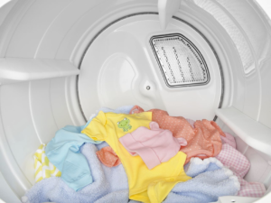
Back in 2009, John La Grou, an electronics innovator, gave a Ted Talk on how to prevent home and office fires with a “smarter type of electrical outlet.” John wanted to look his best. The night before he was to give his Ted Talk, he did a load of laundry. After the wash cycle completed, he threw the load in the dryer and went to bed. Upon rising, he went to the dryer to find that his laundry was still as damp as when he had pulled it from the washing machine.

He only had a few hours before his presentation. In dismay, he Googled the keywords “dryer won’t heat up.” Lacking the time to do any troubleshooting on his own, he called a reputable appliance repair company and was greeted by a kind and patient customer service representative who asked a few basic questions. The inquiries seemed simple, but were
intended to eliminate oversights that could happen to anyone — especially when your mind is overloaded.

When troubleshooting, it’s best to start with the most obvious and simple repairs first, working toward the more uncommon and difficult repairs. The customer service rep wanted to know:

  • Does the dryer run at all?
  • If the dryer does not run, have you looked to see if the dryer is plugged in?
  • If the dryer is plugged in but still does not run, have you checked the circuit breaker switch? There may have been a circuitry overload that tripped a breaker switch.
  • If the dryer is not on a circuit breaker system, have you checked for a blown fuse?
  • Have you checked the selector switch to see if you set it to air dry only?
  • When you open the dryer door, do you smell mold and mildew? This could indicate poor drainage or some type of moisture leak from previous drying sessions and definitely increases the chances of an electrical short. If the washer is leaking, some of that water could have invaded the dryer and become the source of moisture.

Asking these questions may seem redundant, but could save the expense of an unnecessary service call. There are a few reasons for a dryer to not heat; this article focuses on two.

Tools Needed

  • Multi-meter
  • 5/16th nut driver
  • Flathead screwdriver

The multimeter is the most important tool in an appliance repair toolkit. Give particular consideration on checking for continuity. In reference to electrical components, continuity is simply the unbroken flow of electricity from its power source and distributed through the appliance components.

A break in continuity in any part of the electrical system would indicate that electrical current is not flowing to that component. The good news is that if you find a break in continuity, you will usually have found the part that needs to be repaired or replaced.

Unplug the dryer before beginning any work. Be careful while you work around sharp edges and delicate components. You don’t want to cut yourself or damage another component.

Testing the Thermostat for Continuity
The high limit thermostat is actuated by temperature change. It is located behind the back panel and is attached to the heating element. The thermostat must be removed (see below) and tested at room temperature. Testing for continuity will determine if there is an unbroken flow of current. The following guide is for an analog multimeter:

  • Dial the ohms resistance to the smallest possible setting.
  • Calibrate the multimeter by touching the probes together and adjust the display needle to zero.
  • Next, place a probe on either of the thermostat terminals and the other probe on the other thermostat terminal
  • If the multimeter reads zero ohms of resistance, the thermostat has continuity.
  • If the multimeter display needle does not move or change, there is no continuity and the thermostat should be replaced.

Thermostats should show continuity at room temperature and should shut off when heated up. If it doesn’t turn off when heated, the dryer could overheat and increase the chance of a home fire. If the thermostat didn’t test well for continuity, replace it. It’s an inexpensive repair and shouldn’t take longer than 15 minutes to complete.

How to Remove and Replace the Thermostat on a Whirlpool dryer

  • The thermostat is attached to the heating element located behind the back panel.
  • Remove the back panel.
  • Disconnect the wire from the old high-limit thermostat.
  • Detach the thermostat from the heating element terminal – test for continuity (see above).
  • If the thermostat failed, replace it.
  • Position the new thermostat and secure with two screws.
  • Reconnect the wire to the top terminal.
  • Use the wire that came with the thermostat replacement package and connects the thermostat to the heating element.

The thermostat is designed to turn off at high temperature. If it doesn’t shut off when heated, the dryer itself could overheat, increasing the chance of a home fire. This is one reason to not throw your clothes in the dryer and leave the house. Never leave a dryer running while you’re not at home.

Testing the Thermal Fuse for Continuity

  • With a multimeter, set the ohms resistance to the smallest possible setting.
  • Calibrate the multimeter by touching the probes together and adjust the display needle to zero.
  • Next, place a probe on the thermal fuse terminal and the other probe on the other terminal.
  • If the multimeter reads zero ohms of resistance, the thermal fuse has continuity.
  • If the multimeter display needle does not move or change, there is no continuity and the thermal fuse should be replaced.

You won’t be able to determine if a thermal fuse has failed by simply looking at it. It must be removed and tested for continuity.

How to Remove and Replace the Thermal Fuse

  • Disconnect the wires to the old thermal fuse, remove the screw that holds the fuse in
    place, and remove the old thermal fuse.
  • Next, install the new thermal fuse with the mounting screw.
  • Reconnect the wires.
  • Replace the back panel.
  • Plug the dryer back in to make sure it’s functioning properly.

Oftentimes a failed thermal fuse is caused by a clogged venting system. Ensure the venting system is free of lint and any other material that may have inadvertently become lodged inside. It is recommended that you check the venting system after you change the thermal fuse.

To inspect the dryer vents, turn the dryer on and inspect the vent flap to see if it opens when air is being pushed through the system. If it opens, you’re good to go. If not, it means something is preventing air flow to escape. Dryer venting systems should be inspected regularly.

Special thanks to Fred’s Appliance Academy for this helpful tips!

Electric Range Troubleshooting

When you’re in the middle of preparing a tasty meal, you’re likely not giving much thought to the inner workings of your electric stovetop…until something goes wrong that is.  Following is some insight into how ranges work and what could be wrong when you need it the most.

Understanding How an Electric Range Works

The more you know how something works, the easier it is to diagnose problems. While this post centers on electric cooktop repair, it’s helpful to have a basic understanding how the range works:

  • Electricity from a power source is delivered to a terminal block inside the range through three large wires in the power cord.
  • Electrical power is then distributed to components that operate various range features, such as thermostat, heating elements, and  heating coils that comprise most of the cooktop.
  • Heating elements are insulated coils with a metal covering that creates heat and electrical resistance to achieve the desired temperature.
  • Range cooktops come equipped with either a conventional or radiant burner. The radiant burner sits underneath a ceramic surface that was designed for better heat distribution.
  • Each element is supported by its own switch that turns the burner on and sends a message to the thermostat to heat to the desired temperature. The oven is designed to effectively maximize heat and air control.
  • Heat levels are controlled by switches and thermostats. Switches control the on and off, while the thermostat controls the temperature level.
  • One type of switch for electric range tops is an infinite-heat switch, which pulsates power to heating elements on an as-needed basis, maintaining the correct level of heat.

Troubleshooting

#1. Burner Won’t Heat Because of an Electrical Short
Grease and moisture can seep into the power source receptacle of plug-in burners. This can lead to arcing creating an intermittent electrical short that may hardly be noticed. However, the element will eventually burn out.

Solution

  • Regularly clean burner element tips and inside of the receptacle to prevent a burner from shorting.
  • When a heating element must be replaced, be sure to replace the power source receptacle too.
  • Do not immerse the burner in water to clean. The plug-in tips on the burner element contain porcelain and will absorb water. The burner may appear dry, but even a small drop of water could cause serious electrical shock.
  • To prevent cross-contamination, return the same heating element to the receptacle it came from.
  • Use a drip pan to capture grease and oil, but do not line drip pans with foil. The light from the element reflects off the foil back to the element, causing hot spots that will render the heating element useless.


#2. Burned Out Element
Each burner element is controlled by its own switch. When the switch selector knob is turned to a particular heat setting, the switch enables voltage to travel to the element, closing the circuit and causing the element to heat. If the element does not heat, the component has burned out. How to manage this repair:

  • Inspect a conventional element for any blistering or breaks in the coil. If there are visible breaks or bubbling, the circuit has been interrupted and the element needs to be replaced.
  • When inspecting the coils that sit underneath a ceramic top, look for any breaks or burn spots. Replace the coil if any anomalies are visible.
  • If there is no visible damage, check for continuity with a multi-meter.

Solution
Replace the burned-out heating element.

#3. Burned Out Receptacle
If the heating element test proves it is in good shape, assess the power receptacle:

  • Burned out receptacles interrupt voltage sent to the heating element.
  • Inspect contacts for visible burn marks or damage.

Solution
If there is visible damage, replace the power receptacle.

#4. Loose or Burnt Wire Connection
As you work your way through troubleshooting, be sure to look for any loose or burnt wires.

  • It is common for element power supply wires to burn out near the element. If this is the case, you will see visible burn marks. If a wire is loose, try wiggling it back onto its connection.

Solution
Replace damaged or burnt wires, as well as the power receptacle and heating element.

#5. Defective Surface Element Switch
The heating element switch regulates the voltage that controls how much heat is displaced to the coils. When the element reaches the desired temperature, the switch shuts off the voltage. To maintain the designated temperature, this cycle continues throughout the cooking process.

  • A defective switch may prevent the element from working at all.
  • Try simply taking a similarly sized element and plug it in (see below for directions on how to replace a plug-in burner).
  • If the new element fails to work, suspect the switch.

Solution
Replace the element switch.

How to Replace a Plug-in Burner

  •  Plug-in burners are commonly used in General Electric, RCA, Hotpoint, Whirlpool, Frigidaire, and Kenmore ranges.
  • When doing this repair, be careful to avoid any sharp edges.
  • Remember Safety First! Before beginning any work on the range, unplug it from the power source.
  • Once the range is unplugged, grasp the damaged burner by the outer coil, lift it up and pull straight out.
  • Replace the burner by sliding the prongs into the terminal receptacle.
  • Pull the burner forward to lock it in place.
  • Reconnect the range to the wall outlet and turn the new burner switch to on.

Special thanks to Fred’s Appliance Academy for this helpful tips!

CE Tech Tips — June 2018

**NOTICE**

Due the danger and complexity of electronics repair, the following shared technical tips are intended for professional reference only. Please refer to manufacturer’s recommendations as Encompass does not guarantee the accuracy, reliability or safety of this information.

Hitachi TV, 57UWX20B
Reason for Service: Has HV, but no sound or video.
Solution: Found Q445 leaky and replaced.

LG Plasma, 42PJ550-UD
Reason for Service: Set comes on, then turns right back off.
Solution: Look for bad solder on the ZSUS board.  Check L1 and tighten all screws.

RCA TV,  ATC010
Reason for Service: Shutdown, might be intermittent.
Solution: Found an open R835, 120k ohm.

Samsung LCD, LN52A750R1FXZA
Reason for Service:  Dead set
Solution:  Replacing main fuse and Q1815 and 16 fixed the set.   P11NK50ZFP

Samsung HLS5679W
Reason for Service:  No sound
Solution: Replaced several caps.  CM854, CS857, CM860,  2200uF/25V and  C858, C859,  47uF/50V

Sony TV, KDL22L5000
Reason for Service: No remote operation.  The remote itself tests okay.
Solution: Found two shorted caps off pin 3 of the receiver.  C9113 & C9114

Toshiba TV, 27D46
Reason for Service: Intermittent Vert Sweep
Solution:  Replacing D402 fixed the set.

Vizio TV, VO32LFHDTV10A
Reason for Service: Set has no picture but sound okay.
Solution: We found no 12V at the T-Con.  U37 regulator on main bd was bad.  Chip marked 4953GM.

Zenith TV, PV4663MK, Mod 9-1302
Reason for Service:  No picture or raster, sound okay.
Solution:  Had to replace the following:  CRX3412, (NTE577), Horiz Out, QX3200, (2SD2539) and the Fly.  95-4134-29.


Replacing Dishwasher Circulation Pump and Assembly

**NOTICE**
Due the danger and complexity of electronic equipment repair, the following technical tip is intended for professional reference only. Please refer to manufacturer’s recommendations as Encompass does not guarantee the
accuracy, reliability or safety of this information. 

One of the most common service calls involving malfunctioning dishwashers is inability to completely clean dishes. There are many reasons why a dishwasher might stop doing a thorough job. A malfunctioning circulation pump and motor assembly might be the culprit, and it’s one of the hardest parts to reach in the appliance.

What Does the Circulation Pump and Motor Assembly Do?
This piece of hardware controls the flow of water that exits in the dishwasher’s spray arms. It is controlled by the electric system and washer settings, but it’s also a mechanical part that moves and forces water out of the spray arms at different 
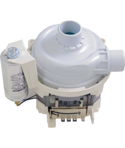
pressure settings. That means there are multiple different triggers that could force the pump and motor assembly to break.

One of the clearest signs of a broken assembly is dirty dishes. If water isn’t hitting the dishes with enough force to rinse away food or soap, then the pump may not be doing its job. However, anything from a poor dish arrangement to clogged holes in the spray arm can cause the same problem. Be sure to investigate other common causes or ask your customer for more details before replacing the part. Once you decide the assembly is at fault, order the replacement part (#1106293 for older Bosch models and 00442548 for Thermador dishwashers.)

Step-by-Step Instructions to Replace Circulation Pump and Motor Assembly:

  1. Unplug dishwasher and turn off water.
    Every appliance repair should start with removal of the power source unless the appliance must be powered on during the job. Replacing a broken circulation pump and motor assembly involves disassembling both wire harnesses and water hoses, so both inputs need to be removed to keep you and the surrounding area safe.
  2. Remove the base and outer door panels.
    For this job you will need to access the dishwasher door’s interior parts. Locate the base panel under the dishwasher door. Loosen the two screws holding the panel in place, and set it aside. To remove the outer door panel, open the door and remove the six screws along the interior perimeter to release the panel. Next, shut the door and pull the bottom of the outer door panel away from the machine. You can then slide the panel down and remove it from the remaining door assembly. Set it aside. Additionally, loosen and remove the inner access panel between the base panel and the outer door panel for complete access to the machine parts.
  3. Pull out the dishwasher.
    Before you move the dishwasher, disconnect the water line and drain hose under the sink. There is probably water in the drain lines so lay down a towel and have a container ready to catch any spills. Then, loosen the two screws and mounting brackets holding the dishwasher in place against the counter top. Grab the sides of the machine and gently wiggle or slide it free.
  4. Disconnect the interior parts around the base of the machine.
    Remove the side covers on the left and right sides of the machine. Then remove the hinge link covers, which are the white plastic panels near the front. Once you set them aside, you will be able to see the door cable hooks that were underneath the covers. Remove them and loosen the screws holding the base of the dishwasher to the cabinet.
  5. Open the machine.
    Remove the lower dish rack and the spray arms. Unscrew the filter bask and fine filter and set them aside. Also, unscrew and remove the spray arm support and the two sump supports before shutting the door. Lay the dishwasher on its back without pinching any loose hoses.
  6. Remove the dishwasher’s base to access the assembly.
    This step involves a lot of disassembly and parts. If each step feels overwhelming or confusing, stop and snap a picture of the details. This will help you reassemble the machine and reverse your steps.Disconnect the sump hose from the water inlet and sump, then twist it out of the way without fully removing it. Gently wiggle the base of the dishwasher so it pulls slightly away from the rest of the machine. This is the section with all of the hoses and parts that you loosened in step five. While you shouldn’t completely remove it, you will need space to remove and install the circulation pump and motor assembly part.

    Remove the drain pump by pressing the latch and twisting it free. Set it aside without removing the attached wire harness. Then, remove the circulation pump the same way. Remove the drain outlet hose. This should let you pull the circulation pump assembly out of the base. Move it carefully and set it on top of the dishwasher without pulling at the attached wire harnesses.

    Clean the sump’s gasket while the machine is open. This step isn’t necessary for the repair, but dishwashers can develop a lot of buildup. It’s unlikely the dishwasher will be disassembled to this extent again, so now is the perfect time for some quick cleaning and maintenance.

    Remove the clamp holding the circulation pump to the heater assembly. If possible, set the clamp aside for later use. However, some clamps are not reusable, so bring a spare clamp with you to the repair site.

    Disconnect all of the wire assemblies. At this point in the disassembly, take a picture. It’s hard to remember where each wire harness should connect to the assembly, and having a picture on hand means you don’t have to worry about incorrect wiring.

    Pull the assembly free of the heating and sump. It should come apart with enough pressure. Then, pry the pump seal away from the top of the part for later use. Also, remove the rubber straps to isolate the circulation pump and motor assembly. The ordered item contains the assembly part only, so you’ll need to save the seals, straps, and, if possible, clamp for reuse on the replacement part. 

  7. Replace Assembly.
    Put the sump seal back in position. Then put the clamp, or a new clamp, on the sleeve for later. Attach the assembly to the heater and sump by the pump ports. If the arms won’t fit, use an approved lubricant or soapy water to reduce the friction. Put the rubber mounting straps back in position and tighten the clamp around the arm. Next, reconnect the wire harnesses in the exact previous configuration.
  8. Insert New Assembly.
    Secure the part inside the base of the dishwasher using the rubber straps. Then, reconnect the sump outlet hose and snap the drain pump back in position. Once it’s aligned, twist in clockwise for a tight seal. Once everything is positioned correctly, push the base of the machine back against the dishwasher. Make sure you aren’t pinching any parts. Then twist the water inlet hose back around and reattach it to its ports.
  9. Reassemble Dishwasher.
    Set the whole machine upright once more. Resecure the base of the dishwasher by inserting and re-tightening the screws in the front and back of the base. Then open the dishwasher door and replace the spray arm parts and filters you removed earlier. Snap the spray arm into position and put the dishrack in the machine. Next, snap the door locks and hinge covers, and side covers back in place on each side of the machine. 
  10. Move Dishwasher Back in Place.
    Carefully push the machine back under the counter and re-secure the mounting screws to lock it in place against the countertop. Then reattach the hoses under the sink. Finish your reassembly by:
    -Screwing in the inner access panel
    -Sliding the outer door panel into place and then tightening the interior perimeter screws
    -Securing base panel

Once you turn on the water connection and power, the dishwasher should now be able to clean each load of dishes without leaving behind residue. Ensure that the machine turns on and the cycle starts properly before completing the job. This repair involves a lot of disassembly, so it’s important to make sure everything is in working order, and that the hoses don’t leak.

Special thanks to Fred’s Appliance Academy for this helpful tip.

CE Tech Tips — May 2018

**NOTICE**

Due the danger and complexity of electronics repair, the following shared technical tips are intended for professional reference only. Please refer to manufacturer’s recommendations as Encompass does not guarantee the accuracy, reliability or safety of this information.

Hitachi TV, 50V500A
Reason for Service:  All front LED indicators continuously flashing in sequence
Solution: Replace lamp

LG TV, 50PG20 UA.AUSVLJR
Reason for Service:  Set intermittently turned off and then sometimes back on
Solution: Found several bad solder joints on U101 regulator on power supply board

RCA TV, 40LA45RQ
Reason for Service: No backlights
Solution:  Replaced Inverter, INV40N14B 

Samsung TV, LN37A550
Reason for Service:  Picture washed out
Solution: If set uses AS15-F or AS15-G chip, replace it.

Sanyo TV, DP42848-00
Reason for Service:  Power light goes off and on
Solution: Replacing the HDMI chip fixed the set.  IC6504, SI19185ACTU

Sony TV, KDL37XBR6
Reason for Service:  No video
Solution:  Replaced open fuse on main, F1422, 5A, and replaced AS15F chip on T-Con.

Toshiba TV, 52HM84
Reason for Service: Bad ballast board
Solution: Replaced open R3, 390k and D2, D3. FMVG2GS

Vizio TV, VO37LHDTV10A
Reason for Service:  Tuner problem, auto program showed all channels but only few HD
Solution: Found bad cap in tuner, 10uF/10V; replacing fixed problem.

CE Tech Tips — April 2018

**NOTICE**

Due the danger and complexity of electronics repair, the following shared technical tips are intended for professional reference only. Please refer to manufacturer’s recommendations as Encompass does not guarantee the accuracy, reliability or safety of this information.

LG TV, 37LG50
Reason for Service:  On Screen Display flashed “This function is not available now.”
Solution: Leaky switch found on the keyboard.  SW108 

Magnavox TV, 37MF321D
Reason for Service:  Dead
Solution: Replaced the following to fix set:  1H00 crystal, 8238.277.36071 & Caps 2H08, 2H09,  2238.869.75478

Mitsubishi TV, VS6051
Reason for Service:  Picture too bright
Solution:  Found bad R9A45, 180 ohm / half W.

Panasonic Plasma,  TC-P50U50
Reason for Service:  Shutdown, 8 blink code
Solution:  Found Q051 shorted on SS board; replacing fixed the set. 

Samsung TV, IN46A500T1FXZA
Reason for Service: Picture too bright, washed out
Solution: Replacing U7 on T-Con fixed set.  AS19-H16.  Note: There is solder under  IC as well as pins. 

Sony TV, KDL40V4100
Reason for Service: Picture too bright
Solution: Replace T-Con or AS15-F IC on T-Con.

RCA TV,  PTK195
Reason for Service:  No video, has HV and filament
Solution: Replace CR14501 near Vert IC. Could also be Vert IC; turn up G2 to see if Vert is collapsed.

Toshiba Combo,  MW27H62
Reason for Service:  Intermittent shutdown, red light goes out
Solution:  Replacing Digital board with #72783951 fixed set.

Vizio TV,  E320VL
Reason for Service:  Set comes on, logo goes from amber to white, then shuts down
Solution: Replacing U18 EEPROM fixed set.


Replacing Terminal Block on Whirlpool Oven

**NOTICE**
Due the danger and complexity of electronic equipment repair, the following technical tip is intended for professional reference only. Please refer to manufacturer’s recommendations as Encompass does not guarantee the
accuracy, reliability or safety of this information. 

The oven terminal block provides a safe connection between the power cord and wiring. If it burns out or any of the terminals break, the part needs to be replaced. Order part number 8203546 for your Whirlpool oven and follow these steps:

1. Unplug the oven or flip the circuit breaker. This repair focuses solely on wiring and electrical parts, so there should be no power
flowing to the appliance.
2. Remove the access panel on the terminal pull. Pull the oven away from the wall and move to the back of the appliance. Locate the
square access panel on the lower half of the back and remove the two screws holding it in place. Lift the panel away.
3. Remove the wiring around the terminal block. Take out the three nuts holding the terminal block in place. Next, pull the three bottom
wires away from the terminals and fold them to the side. Next, remove the top wiring. Take a picture of the wiring before you start so you remember the configuration. After that, loosen the screw holding the grounding strap in place around the middle terminal and remove.
4. Remove the terminal block and install the new one. Loosen the two screws holding the block in place and set them aside. Next, pull the
terminal block free of the box. Hold the new part in place and align it with the screw holes. Tighten the two screws.
5. Reattach the wiring. In this step, work backward from how you removed the wiring in Step 3. Begin by inserting the ground strip around the middle terminal and re-securing the screw. Then, slip the black, white and red wiring in place from left to right and put the nuts back in position. Next, reattach the bottom wire clamps to each terminal and tighten the second set of nuts. Ensure all of the connections are tight, especially the grounding strip.
6. Put the access panel cover back in place. Slip the square cover over the terminal block and re-tighten the two screws holding it in
place.

Special thanks to Fred’s Appliance Academy for this helpful tip.

Whirlpool Dishwasher Pump Replacement

**NOTICE**
Due the danger and complexity of electronic equipment repair, the following technical tip is intended for professional reference only. Please refer to manufacturer’s recommendations as Encompass does not guarantee the accuracy, reliability or safety of this information. 

When a dishwasher won’t clean dishes, one of the first likely causes is the pump outlet. This part connects the main water supply tube to the pump and spray arms. If it cracks, water pressure decreases and will not properly shoot out of the spray arms to effectively wash food particles away. Here’s how to fix a Whirlpool dishwasher in just a few minutes with replacement part 8194582.

1. Unplug appliance. Even though this repair doesn’t involve electrical components, unplugging or flipping the circuit
breaker to major appliances (especially major appliances with water) better ensures your safety.
2. Access spray arms. Open the dishwasher door and remove lower rack. Unscrew spray arm central piece and fully remove, along with arms and bearings. One metal bearing is in the spray arm apparatus, and the other is below resting on the pump outlet.
3. Remove pump outlet. There are eight screws holding the pump outlet in place below the spray arm apparatus. Use a
screwdriver to remove the screws. Set them aside for later use since the replacement parts do not come with replacement screws. Disconnect from supply tube. Remove the old pump seal with flathead screwdriver.
4. Install replacement part. Put seal in housing and connect pump outlet to water supply tube. Make sure outlet is aligned with holes and screw into position.
5. Put the dishwasher back together. Reinstall bearings and spray arm apparatus. Make sure it spins with friction or tension.

Special thanks to Fred’s Appliance Academy for this helpful tip.

CE Tech Tips — March 2018

**NOTICE**

Due the danger and complexity of electronics repair, the following shared technical tips are intended for professional reference only. Please refer to manufacturer’s recommendations as Encompass does not guarantee the accuracy, reliability or safety of this information.

AIWA Stereo, AV-D57U
Reason for Service: Display very dim (unviewable)
Solution: Found bad C123 in the power supply; fixed the unit.  220uF/25V

Emerson TV,  LC220EM1
Reason for Service:  Picture cycles through Red, Green and Blue Screens.
Solution: Using the remote, push R cursor, L cursor, Up then Down.

Insignia TV,  NS-32E320A13A
Reason for Service:  Dead, no standby
Solution:  Found an open resistor in power supply that fixed the set. R9317, 1.5M 

Philips TV,  37MF321D/37
Reason for Service:  Shutdown with power light blinking
Solution:  Replacing D6079 on power board fixed the set.  9.1V, half W zener

Sony TV,  KD-36XS955
Reason for Service:  Instant shutdown with 3 blink code
Solution:  Shorted mylar cap, C598, on the AY board, off pin 10 of audio amp IC.   0. 1uF/50V,  #113049511

Toshiba TV,  55G310U
Reason for Service:  Dead set
Solution:  Found Q101 and 102 bad in power supply.  FQPF13N50C.  Main fuse also bad.

Vizio TV, VO32LFHDTV10A
Reason for Service:  Sound okay, but no picture
Solution: No 12V to the T-Con.  Found U37 regulator IC Bad.  Chip marked 4953GM

Zenith TV, PV4663MK
Reason for Service:  No HV, but audio okay
Solution: Replaced the Fly, Vert Out LA7838 and burnt 3.3 ohm resistor near the fly.