Author - wpengine

CE Tech Tips — April 2020

**NOTICE**
Due to the danger and complexity of electronic equipment repair, the following technical tip is intended for professional reference only. Please refer to manufacturer’s recommendations as Encompass does not guarantee the accuracy, reliability or safety of this information. 

Emerson TV, IC401EM2F
Reason for Service: Dead
Solution: Found shorted zener, D1208B and open 8A fuse.

Hitachi TV,  53SDX01B
Reason for Service: No audio
Solution: Replaced open relay, S904.

LG TV, 47LS4500
Reason for Service: Won’t turn on, 3 blink error
Solution: Replaced D603 on power supply.

Philips TV, 50PF7321D-37
Reason for Service: Dead, 6 blink error
Solution: Replaced C8014, 33uF/450V.

Samsung TV, HL72A650C1FXZA
Reason for Service: Set cycles off and on
Solution: Replaced ballast cap 47uF/450V and two 200V caps in power supply.

Samsung TV, UN32EH4003
Reason for Service: Set plays for a while then intermittently shuts down
Solution: Replaced CM867 in power supply.

Sony TV, KDL46EX500
Reason for Service: Powers on then shuts down with 6 blink code
Solution: Replaced power supply, 147420511.

Toshiba TV, 32CV510U
Reason for Service: Dead set
Solution: Replaced Q860, STRZ2589 and open fuse F820.  2A.

Fix for Continuous Clicking Sound in Gas Cooktop

**NOTICE**
Due to the danger and complexity of electronic equipment repair, the following technical tip is intended for professional reference only. Please refer to manufacturer’s recommendations as Encompass does not guarantee the accuracy, reliability or safety of this information. 

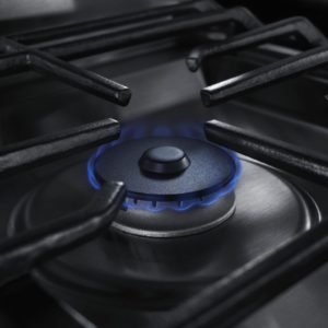
Click, click, click – it’s the sound you expect to hear for a few seconds when turning on a gas stove.
However, you definitely don’t expect to hear this well after the burners are lit or after you
shut them off. If a clicking sound continues when the stove is supposed to be off, it’s actually not as big of a problem as you would expect.

The clicking sound is caused by the spark electrode on a gas stove creating small sparks. During normal function, these sparks meet with released gas and ignite to create a flame. When it clicks outside of ignition, it may or may not be releasing sparks.

Regardless, if the gas is not turned on or there is no gas leakage, it’s not particularly
dangerous, just noisy. If you do suspect there may be a gas leak, stop what you’re doing immediately and call for emergency service.

How to Stop Clicking Before Repair

To stop the clicking sound, disconnect the gas stove from electricity — in most cases, this will
be done at the circuit breaker. Without electricity, the spark electrode will stop sparking or clicking.
When investigating further, be sure to shut off the gas as well for safety.

What Causes Gas Stove to Click?

When troubleshooting a gas stove that won’t stop clicking, the cause likely isn’t something that needs to be repaired, but there are a few parts that can go faulty and will need to be replaced.

Stove is Dirty or Damp

This is probably the most likely cause of clicking issues, and luckily, it’s usually the easiest fix. The stove may have accumulated food particles during the cooking process over time, which can work their way into the burner head. This is also the case if a pot boiled over or excess water dripped onto the stove. If food or moisture reaches the spark electrode, it will click. In many cases, the food and moisture will just burn away, and the clicking will stop. If clicking starts or even stops in the middle of cooking, this is the likely cause.

If the clicking didn’t stop, unplug the stove and start cleaning. Dry the stove and inside the burners as much as possible. For food particles, clean the burner head thoroughly, including inside the slots that release gas. To clean these, use a bit of sturdy wire or something that doesn’t have a risk of breaking and getting lodged.

Unfortunately, if the burner got wet, it might take awhile for clicking to stop. The stove needs to dry completely by leaving it unplugged for a few hours to allow moisture to evaporate naturally.

Spark Ignition Switch is Faulty

The switch that controls the flow of electricity to the spark electrode is located immediately behind the control knob for each burner. If this switch is not functioning properly, it can cause continuous clicking or stop working in an electrode. If it clicks, the flow of power is stuck on.

While each burner has a separate switch, it is usually connected via a harness, requiring every switch to be replaced. However, it’s a simple repair usually just involving removing the knobs and lifting the cooktop to access the inner workings.

Spark Module is Faulty

Once the switch allows the flow of power, the next step in the spark-producing chain is the spark
module, which directs voltage to the electrode. This part can also malfunction and result in  constant clicking. If the switches have been tested with a multimeter and they check out, this is the next part that should be tested. Unlike the switches, there is only one spark module for all gas burners. If it’s faulty, resulting in constant sparking, it’s likely that each burner is sparking. If this is the case, the small module will be located under the gas cooktop or in the back of the gas range.

Spark Electrode is Faulty

The spark electrode is the final part of the chain. It’s the part that actually creates the spark that ignites the gas and is usually the least likely to go faulty. If clicking has been continuous, a malfunction here becomes more likely. The more your gas stove clicks, the more worn this particular part becomes. Although this is the least likely part to go faulty, it is also the most difficult to replace. The gas burner must be disassembled to access and remove the spark electrode and install a new one.

Special thanks to Fred’s Appliance Academy for this helpful tip!


Replacing Ice Maker Bucket in Whirlpool Refrigerators

**NOTICE**
Due to the danger and complexity of electronic equipment repair, the following technical tip is intended for professional reference only. Please refer to manufacturer’s recommendations as Encompass does not guarantee the accuracy, reliability or safety of this information. 

If the ice maker bucket of a Whirlpool, Kenmore, Kitchenaid or Maytag freezer breaks, it can be replaced without having to buy a new refrigerator or ice maker.  Fortunately, the refrigerator panel doesn’t have to be opened to perform this fix. If you’re handy with a pair of needle-nose pliers, you can replace the bucket of a Whirlpool ice maker.

Supplies

In addition to a replacement ice maker bucket for the correct product model number, needle-nose pliers and a screwdriver are needed for this job. The type of screw cap differs by model, so a combo wrench or socket screwdriver kit is recommended.

â—Ź Replacement Ice Maker Bucket
â—Ź Needle-nose Pliers
â—Ź Towel
â—Ź Screwdriver or Combo Wrench
â—Ź Flat Work Surface

Remove the Ice Bucket

  1. Pull Out Entire Bucket Assembly
    Removing the ice bucket is easier than it looks. Simply grasp it firmly and pull the entire
    assembly out and away from the freezer back panel, detaching it from mechanical coupler.
  2. Place On Flat Work Surface
    Lay towel over work surface, and position ice bucket upside down. The opening should be facing table showing a thin metal post secured along underside of ice bucket.
  3. Detach Actuator Arm
    The actuator arm is the metal bar across the now top of the ice bucket assembly. It attaches bucket to rest of assembly and will need to be detached from bucket before continuing.
  4. Release Arm Spring 
    Use needle-nose pliers to grasp small spring wire in groove of plastic arm stand. Pull wire away to release spring. Twist spring to release other side.
  5. Remove Retainer Bracket and Screws
    Unscrew screws holding bracket onto arm stand. Pull entire retainer bracket away and set  aside with the screws. This will release actuator arm.
  6. Remove Screws Inside Ice Bucket
    Flip ice bucket up on heavy end, with auger tip pointing up. You should be able to see two screws inside bucket that are securing it to the auger assembly. Remove these screws and the ice bucket will loosen.
  7. Pull Out Old Ice Bucket
    Removing the ice bucket is tricky. Carefully guide it out around the metal auger until it can be
    pulled away free. Discard ice bucket once it’s loose.
  8. Install New Ice Bucket
    Unpack new ice bucket, ensuring removal of all small pieces of packaging that may be fitted around small, thin or protruding pieces.
  9. Guide Bucket Around Auger
    Installing new bucket requires same maneuver in reverse. Carefully guide new ice maker bucket in and around auger spiral until it can set into housing.
  10. Screw into Assembly Housing
    Settle new ice bucket into assembly housing, and retrieve screws just removed. Tighten screws firmly to ensure bucket does not come loose later when it’s full of ice.
  11. Align Actuator Arm with Mounting Stand
    Move actuator arm back into place to rest on arm stand of new ice bucket. The spring should be on outer side of stand as it was before.
  12. Set Retainer Bracket over Actuator Arm
    Retrieve actuator arm retainer and place over arm on new stand. Reinstall screws and tighten securely.
  13. Wind Actuator Spring into Place
    To get spring back into place, turn actuator spring counterclockwise. Carefully set securing wires into place. Use needle-nose pliers if needed.
  14. Return Ice Bucket
    The final step is placing entire ice bucket assembly back into the refrigerator. Once this is
    done, the ice maker should return to normal function.
  15. Slide Ice Bucket Assembly into Place
    Once new ice bucket is fully secured to assembly, put the entire assembly back into the fridge. Fit assembly back into its slot, but don’t press in yet.
  16. Rotate Auger to Seat Coupler
    If assembly doesn’t fit perfectly at first, manually turn auger until the mechanisms fit together. Because this is an entirely mechanical piece, line up gears for assembly to fit into place.

Special thanks to Fred’s Appliance Academy for this helpful tip!


CE Tech Tips — November 2019

**NOTICE**
Due to the danger and complexity of electronic equipment repair, the following technical tip is intended for professional reference only. Please refer to manufacturer’s recommendations as Encompass does not guarantee the accuracy, reliability or safety of this information. 

Hitachi TV, 57UWX20B
Reason for Service: Freezing or any unusual eeprom or micro suspected problem
Solution: Add jumper from I007 pin 1 to cathode of D019.

LG TV, 47LD520-UA
Reason for Service: After set warms up, starts cycling off and on
Solution: Found and resoldered many bad solder joints around Q707, 708, 709, 710.

Panasonic TV, TCP50U2
Reason for Service: Dead, 10 blink error code
Solution: Changed mail board to repair.

Samsung TV, LN-T2353HX
Reason for Service: Set won’t start, but has power light
Solution: Found open CM802 in power supply: 18nF/630V (box cap).

Samsung TV, PN64D550
Reason for Service: Dead set
Solution: Found two burned caps in power supply: C816 & C817.  Also found bad solder on many components in power supply.  Examined and resolderd.

Samsung TV, IN40A530P1FXZA
Reason for Service: Bad video, audio screeches, starts slow
Solution: Replaced C102 and C131.

Sony KDL52W4100
Reason for Service: Picture has some faint blocks in center of screen, which go away after warm up
Solution: Replaced T-Con.

Sony TV, KDL40BX450
Reason for Service: Dead set, no standby
Solution: Replaced main board.


Replacing Freezer Temperature Control Thermostat in Frigidaire Refrigerator

**NOTICE**
Due to the danger and complexity of electronic equipment repair, the following technical tip is intended for professional reference only. Please refer to manufacturer’s recommendations as Encompass does not guarantee the accuracy, reliability or safety of this information. 

The freezer temperature control thermostat, or cold control thermostat, regulates the temperature inside the freezer compartment. When the thermostat senses the freezer is too warm or too cold, it cycles the compressor on and off. The control thermostat is found in the control housing inside the fresh food compartment of the Frigidaire refrigerator model FRS26R4CW.

The sensor bulb, which monitors the temperature, stretches from the control thermostat to the
freezer interior. If the freezer runs too cold or too hot, there’s a good chance the
temperature control thermostat has failed and is no longer switching the compressor on and off
at the appropriate time. Unfortunately, a damaged control thermostat cannot be repaired and
will need to be replaced.

Appliance Repair Safety Tips

  • Always unplug refrigerator and turn off its water supply before starting work to prevent electrocution injury.
  • Keep hands and eyes safe by wearing gloves and safety goggles during repairs.
  • Stop what you’re doing and contact an appliance repair specialist if ever a repair job feels unsafe.

Tools Needed

  • 1/4″ Nut Driver
  • Flat head screwdriver

Steps to Removing Control Housing Assembly from Refrigerator

  1. Open fresh food compartment door and either lower or remove top shelf. Once
    shelf is out of the way, unscrew refrigerator light bulb.
  2. At front of control housing assembly, depress water filter release button. When filter pops out, remove it.
  3. Using 1/4″ nut driver, unthread screw that secures water line cover to top and rear wall of  refrigerator. Then, carefully pull cover off wall and ceiling, and disconnect from back of control housing assembly.
  4. Now, unthread screws that hold control housing assembly to compartment ceiling and sidewall. There are several screws, so ensure all are removed, including the one behind the damper grill. Once all screws are removed, lower control housing and disconnect wire plug from ceiling.
  5. Next, pull out the two water lines that run to the back of the control housing. Some water
    may leak out of the lines, so have a towel nearby.
  6. Finally, pull out the temperature control sensor bulb from freezer compartment. Move control housing assembly to flat, sturdy work table.

Uninstall Freezer Temperature Control Thermostat

  1. Start uninstalling temperature control thermostat by removing control knob. To do
    so, insert flat head screwdriver behind knob and push off the control thermostat shaft.
  2. Next, remove control thermostat from mounting bracket by using flat head screwdriver to depress locking tab holding component in place. Then, lift thermostat up and disconnect wires running to it.
  3. Before completely uninstalling control thermostat, free the sensor bulb, which runs along side the damper control. To get to the part, pull top of damper control off control housing. Then, carefully slide sensor bulb out of the plastic installation tube.

Installing New Freezer Temperature Control Thermostat

  1. Take new control thermostat and straighten out sensor bulb. Then, thread bulb through plastic installation tube attached to side of damper control. Stop sliding sensor bulb forward once tip of the bulb reaches the end of the tube.
  2. Reinstall damper control by pushing it back onto control housing assembly.
  3. Insert rest of the sensor bulb into clips running along the inside of the control housing. Then, near the temperature control, bend the sensor bulb to fit the component back into mounting bracket.
  4. Before pushing control thermostat into bracket, reconnect wires to terminals. Then, use flat head screwdriver to pull back bracket locking tab while pushing down on control thermostat until the component locks in place.
  5. To complete installation, slide control knob onto thermostat shaft. Test knob out by twisting it around a few times to ensure it rotates freely.

Reinstalling Control Housing Assembly

  1. Begin installing control housing assembly by threading sensor bulb through opening near back of fresh food compartment. Then, insert control housing plug into refrigerator ceiling. Next, push water lines into back of the control housing assembly.
  2. Line up screw holes on control housing assembly with screw holes in fresh food compartment ceiling. Then, using 1/4″ nut driver, rethread screw closest to water filter housing. Once that screw is secure, reinstall the rest of the screws. Before finishing, insert screw near water lines and behind damper grill.
  3. Retrieve waterline cover and reinstall by inserting tabs on front of cover into slots on back of water filter housing. Then, push up on cover to insert locking tabs into the refrigerator ceiling. Finish installing cover by rethreading single screw holding it to rear wall.
  4. Slide the refrigerator water filter back into its housing. Replace fresh food compartment light bulb, and readjust top shelf.
  5. Finally, plug in the refrigerator and turn on water supply. Open refrigerator door and set control thermostat to desired temperature. Give some time for the new part to start working and then check to ensure the temperature is now working correctly.

Special thanks to Fred’s Appliance Academy for this helpful tip!


CE Tech Tips — October 2019

**NOTICE**
Due to the danger and complexity of electronic equipment repair, the following technical tip is intended for professional reference only. Please refer to manufacturer’s recommendations as Encompass does not guarantee the accuracy, reliability or safety of this information. 

Hitachi TV, 53FDX20B
Reason for Service: Dark picture, maybe also missing a color
Solution: Clean spark gaps; CRT pins and socket on CRT board.

Panasonic TV, PT44LCX65
Reason for Service: Dead, no lights
Solution: No 5V standby. Found bad 5 pin 5V regulator on bottom board.

Philips TV, 42PF5321D/37
Reason for Service: Set won’t start; both red and green LEDs flash
Solution:  Found bad C8014 in power supply. 33uF/450V

Samsung TV, HL50A650C1FXZA
Reason for Service: Set works for short time, then lamp turns off and back on intermittently
Solution: Found bad D803 in power supply.  UF4007

Samsung TV, LN40D630M3FXZA
Reason for Service: Dead set
Solution: Replacing UN8015, (STRW60525) and RM811, 0.36 ohm/2W in power supply fixed set.

Samsung TV, PN50C550
Reason for Service: No picture
Solution: Visually found damage on one of the buffer ICs.  Replaced buffer assembly. LJ41-06755A 

Sony TV, KDL52W4100
Reason for Service: Vertical lines in screen and poor contrast
Solution: Replaced T-Con. 

Toshiba TV, 40E200U1
Reason for Service: Backlights work intermittently
Solution: Replaced inverter module. Toshiba 75017117


CE Tech Tips — September 2019

**NOTICE**
Due to the danger and complexity of electronic equipment repair, the following technical tip is intended for professional reference only. Please refer to manufacturer’s recommendations as Encompass does not guarantee the accuracy, reliability or safety of this information. 

Hitachi TV,  42HDS52A
Reason for Service: Loud buzz comes from right speaker, nothing from left.
Solution: Replacing sub digital board fixed set.

Mitsubishi TV, WD-65835
Reason for Service: Dead set, no LEDs blinking or on.
Solution: If 12V and 21V supplies are okay, replace main board.

Panasonic TV, TH-50PZ77U
Reason for Service: 12 blink error code
Solution: Might be bad speaker. Ohm them and if one is low, unplug speaker and try set again.

Philips TV, 50PF7321D/37
Reason for Service: Dead set, clicks when plugged in.
Solution: Found two bad caps on power supply board: C8059 and C8060. Both 3300uF/10V.

Samsung TV, LN46D550K1FXZA
Reason for Service: No backlights
Solution: Replaced inverter board: 27-D056702

Sharp TV, LC-C3242U
Reason for Service: No power.
Solution: Check for shorted 5W/150V zener in power supply.  Also check R7002, 2.2ohm/half W.

Sony TV, KDL55EX621
Reason for Service: Shuts down with two blink error code.
Solution: Replaced Q6602 & Q6603 on G8 board, and R6540 on G6 board.  0.1ohm/half W.

Vizio TV, E421VA
Reason for Service: When set turned on, logo goes from amber to white for just a second, then the set shuts down.
Solution: Replacing the power supply fixed the problem.


CE Tech Tips — August 2019

**NOTICE**
Due to the danger and complexity of electronic equipment repair, the following technical tip is intended for professional reference only. Please refer to manufacturer’s recommendations as Encompass does not guarantee the accuracy, reliability or safety of this information. 

Hitachi TV, 46UX12B
Reason for Service: Set shuts down.
Solution: Replaced Q401 & D441.

Panasonic TV, TC–P50X5
Reason for Service: Dead set, no power.
Solution: Replacing U203 on foil side of board fixed set.

Pioneer Pro150FD TV
Reason for Service:  Dead, two blink error.
Solution: Replaced power supply.

Samsung TV, PN64E533D2FXZA
Reason for Service:  Dead set, main fuse was blown.
Solution: Replaced shorted QS802, QS804 on power board.

Samsung TV, PN64E533D2FXZA
Reason for Service: Dead set.
Solution: Found two bad FETs: QS802 & QS804. Fuse also blown: F801.

Sanyo TV, DP50749-01
Reason for Service: Dead set.
Solution: Found shorted IC301, STR-W6252 and open fuse, 302, 1A. Replacing both fixed set.

Visio TV, VP50HDTV10A
Reason for Service: No picture, no prime but has audio.
Solution: Found open resistor, R135, on Y-SUS.  1ohm/5W ceramic.

Westinghouse TV, TX-42F430S
Reason for Service: Won’t turn on, but standby okay.
Solution: Replaced cap TC51 in power supply, 470uF/16V.

LG Dryer Faulty Gas Burner Valve Assembly

**NOTICE**
Due to the danger and complexity of electronic equipment repair, the following technical tip is intended for professional reference only. Please refer to manufacturer’s recommendations as Encompass does not guarantee the accuracy, reliability or safety of this information. 

How to Replace a Faulty Gas Burner Valve Assembly in a LG Dryer

If clothes are still wet after completing the dry cycle in LG dryer model DLG2602R, it is likely due to lack of heat. This is a common dryer issue that could be caused by numerous possible malfunctions.

Once determining there are no issues with the high limit thermostat, flame sensor, thermistor and ignitor, consider examining the gas burner valve assembly, which supplies gas to the dryer burner. A malfunctioning valve assembly won’t administer gas, which means the dryer won’t heat.

Before starting any dryer repairs, unplug it from the wall and turn off the gas supply valve. Never attempt a repair without wearing proper safety gear, such as work gloves and goggles. As with all technically difficult and potentially dangerous repair, this repair is best left to a
specialist.

Steps to Replacing Gas Burner Valve Assembly

  1. Pull LG dryer forward and away from laundry room wall. On the back of the appliance, unthread screws that secure the top panel to  dryer. Once screws are out, pull panel toward you, and lift it up and off dryer.
  2. Now, disassemble the control panel. (Before disconnecting wires, it’s a good idea to take a photo of all wire connections to assist in easily reconnecting them during reassembly.) Start detaching the wire harnesses from the back of the board. Once all wires are disconnected, take out the screws that hold the control board console to the dryer, and then pull console off front of dryer.
  3. With control board removed, disconnect the door switch located near the top center of the door frame. Next, open dryer door and
    unthread screws that hold front panel to lint screen housing. Once the screws are out, close the door and unthread screws at the top of the front panel. Then, carefully tilt front panel backward, and pull it up and off dryer.
  4. Now, remove control panel bracket off the dryer. First, locate dryer light bulb and disconnect wire harness running to it. Next, locate two wiring retaining clips on the back of the bracket. Take out the wires being held in the retaining clips. Then, remove screws holding the control panel bracket to the front of dryer, and pull bracket off dryer.
  5. Near the bottom of dryer, disconnect wire harness to the moisture sensor. Once the wires are separated, unthread screws that
    secure bulkhead to dryer and carefully lift off.
  6. Reach in between dryer floor and dryer drum to take drive belt off idler pulley and drive motor pulley.
  7. Grab drive belt on top of dryer drum and use to help guide drum out of dryer cabinet.
  8. With drum removed, locate gas burner valve assembly in the cabinet’s lower right hand corner. Disconnect wire harnesses running to valve assembly terminals. With a Phillips screwdriver, unthread screws that secure gas line to burner valve. Once screws are loose, carefully pull gas line off burner valve. Next, take out screws holding valve assembly to mounting bracket, and then take gas burner valve off mounting bracket and out of dryer cabinet.
  9. Before installing new valve, take the orifice off the old gas burner valve and place on new component. Once orifice is securely
    attached to the new gas burner valve assembly, proceed with installation process.
  10. Place gas burner valve assembly on mounting bracket, ensuring screw holes are lined up on bracket with screw holes on the valve
    assembly. Then, replace screws used to secure gas burner valve to mounting bracket. Next, align gas supply tube with burner valve, and insert tube into the valve. Once tube and valve are connected, rethread screws taken out earlier to secure the tube to the valve. To complete installation, reconnect gas burner wire harnesses to valve terminals.
  11. Before putting dryer back together, take a moment to check for any gas leaks. To do so, fill a spray bottle with soapy water, and turn  gas supply valve back on. Then, spray gas burner valve with soapy water. If any bubbles form, a gas leak is present, meaning the connection is not tight enough. At this point, turn off dryer’s gas supply, and try tightening the tube and valve coupling. Once you’ve adjusted the union, turn gas back on, and run gas leak test again. If no bubbles appear, the gas leak should no longer be an issue. If bubbles are still forming, DIY consumers should contact a dryer repair technician to further inspect.
  12. After testing for leaks and none are found, turn off gas running to the dryer, and start reassembling the dryer. Pick up dryer drum and carefully guide it into the dryer cabinet, ensuring the drum back sits on the drum rollers. Then, reach in between the drum and dryer floor to rethread drive belt on idler pulley and drive motor pulley. Make sure belt is installed in zigzag formation.
  13. Retrieve dryer bulkhead, and align with front of dryer. Then, secure part with screws taken out earlier. With bulkhead in place,
    reconnect moisture sensor wire harness, and light bulb wire harness.
  14. Now, reattach control board bracket. Once bracket is in place, pull door switch wire harness to front of dryer through one of the
    openings on the bracket. Then, snap wire into retaining clips on back of the bracket.
  15. Grab dryer front panel and line up with the dryer front. Before laying panel flush, reconnect door switch harness to door switch, and
    finish installing front panel. After adding screws to secure panel, open dryer door, and rethread screws that connect front panel to lint screen housing.
  16. Snap control panel back on dryer, and reattach screws removed earlier. Finish installing control panel by reconnecting wire harnesses that run to the panel back.
  17. Finally, reinstall the dryer’s top panel, plug in the dryer and turn on gas supply valve.

Special thanks to Fred’s Appliance Academy for this helpful tip!


CE Tech Tips — July 2019

**NOTICE**
Due to the danger and complexity of electronic equipment repair, the following technical tip is intended for professional reference only. Please refer to manufacturer’s recommendations as Encompass does not guarantee the accuracy, reliability or safety of this information. 

Hitachi TV, 57UWX20B
Reason for Service: Shuts down.
Solution: Horz output voltage and B+ okay; Horz output transistor collector has distorted waveform.  Replace TH01.

JVC TV, LT32DM20
Reason for Service: Set starts with OSD showing input, then shuts down.
Solution: One of the inverter transformers was bad; replacing it fixed the set. Found it by comparing to other transformers.

Panasonic TV, TH-50PZ80U
Reason for Service:  No picture or OSD after powering on; power light lit.
Solution:  Replacing A board fixed set.

Samsung TV, HLP5085WX/XAA
Reason for Service: Set makes squealing noise when powering on.
Solution: Replaced C540, 1uF/50V SM cap on DMD module.

Samsung TV,  LN-T3753HN
Reason for Service: At turn on, backlight flashes for short time, then no more backlight.
Solution: Replaced inverter.

Sony TV, KDL46W5150
Reason for Service: Set comes on for 10 seconds, then shuts down. Does this three times then gives 10 blink error code.
Solution: Try factory reset.  Turn power on, then immediately press and hold arrow up and press and release power button.

Vizio TV,  VP322HDTV10A
Reason for Service: No audio.
Solution: Replacing SM Q15 fixed problem.

Westinghouse TV, LD-3255VX
Reason for Service: Dead set.
Solution: Replacing U13/14 eeprom fixed set. TW61301-K032A69